It is not easy to second-guess a designer, as normally there are many interrelated factors that were considered, which a modder may not all have sight of. So yes, superfluously it seems often very easy to improve a part of a design without it doing anything else to the complete unit except increase the price ;-)
Jan
Jan
It is not easy to second-guess a designer, ...
Jan
i guess that a reasonable approach is to look first with a spectrum analyzer where the issues are and then add an extra regulation stage or passive filtering that tackle those issues ? and of course check with the analyzer if the issues have been solved
One point that i was not considering enough is the PSRR of the amp circuit i guess it can vary a lot from one design to another
And i have just a feeling that in order to get high PSRR a more complex amp design is needed ?
Supplying extremely clean (noise free) voltage to the circuit can make a low PSRR less of a problem ?
Usually lower psrr is associated with class a amplifiers which in itself is a benefit for the power supply simplicity as it can be a simple capacitor multiplier due to the much more constant current draw of the class a. If you master the grounding and wiring you often need no regulator at all.At least i could build tape preamps and phono preamps with no regulator at all and i couldn't hear any weird noise ..Op-amps have very high psrr by themselves.Marantz cd5000 was the first thing i saw exploiting that...no regulator on the analog side ,just a first order rc decoupling network after the filter capacitor.
Last edited:
Usually lower psrr is associated with class a amplifiers which in itself is a benefit for the power supply simplicity as it can be a simple capacitor multiplier due to the much more constant current draw of the class a ...
I see. But maybe a class A amp would sound even better with a regulated (i.e. lower ripple) power supply ? have you tried that ?
Yes, definitely (to almost all the questions).i guess that a reasonable approach is to look first with a spectrum analyzer where the issues are and then add an extra regulation stage or passive filtering that tackle those issues ? and of course check with the analyzer if the issues have been solved
One point that i was not considering enough is the PSRR of the amp circuit i guess it can vary a lot from one design to another
And i have just a feeling that in order to get high PSRR a more complex amp design is needed ?
Supplying extremely clean (noise free) voltage to the circuit can make a low PSRR less of a problem ?

Thanks and great ! i am starting to clear out my mindYes, definitely (to almost all the questions).
Another couple factors in the designer's choice of Emitter-load / Collector-load (in regulator circuits using an op-amp and series-pass transistor):
- the output swing of the op-amp may be a consideration; if the op-amp is to be powered by the resulting regulated supply, it's output will need help (bias or level-shifting) to forward bias a Base-Emitter junction (Emitter-loaded); bias will increase its output stage dissipation
- it is likely less the 'gain difference' as much as the 'inherent stiffness' of a forward-biased Emitter, compared to a Collector; suppose with the Emitter-loaded design, that the Base simply remains stationary -- any changing load on the Emitter is 'discouraged' by a sharp counter increase/decrease in conductivity. In a Collector-loaded design, it can wander all over the place with very little change in the transistor's desire to conduct.
I suspect the first item is the more important factor in the Kenwood designs mentioned earlier - the one that used both configurations in different supplies.
Cheers
Last edited:
I remember a very old article (probably in ETI at the time) from Stan Curtis, similar discussion for a power amp. One with a common emitter output stage, with the output collectors being the output, and the other with common collector stage, the emitters being the output.
Open loop, you see quite a difference in output impedance, IIRC the collector outputs were 60 ohms, the emitter outputs were a few ohms only. But when you close the feedback loop the differences become so small that it's almost impossible to measure. This is exactly what happens in these regulators.
So, yes, I agree to your reasoning, but at the end of the line the differences are so inconsequential that other considerations may dictate which configuration to prefer. Engineering being the art of picking the best compromise ;-)
Jan
this was my first thought when i showed this schematic difference.In a Collector-loaded design, it can wander all over the place with very little change in the transistor's desire to conduct.
Engineering being the art of picking the best compromise ;-)
Jan
Usually i tend to be religious about Kenwood, but the L-A1 amp single compromise seems to be dictated by the lack of high FT final transistors on the market...as their quadrive concept was aimed at having the best linear response with low FT transistors.There was a period of about 20 years where high 80...90 Mhz FT transistors ceased to be produced, as well as their powerfull 200Mhz drivers probably because Sanyo and Sanken were deep into their STK hybrid line of amplifiers digging the grave for all other commercial atempts and that made the Accuphase's decision to base their best models exclusively on diamond buffer output.They knew that nohing compares with a faster design. Some STK darlington or full amp chips perform fantasticaly well and i think they have very fast transistors inside as well. Naim's recent designs went the same way (50...60mhz output transistors as unfortunately 80-90 MHZ- output transistors seem to be lost forever).Those who own the faster L-series amps that came 15 years before L-A1 know that L-A1 wasn't beter .
Other than that, i mentioned in several other topics that the most genious audio amplifier designer in my view was Patrick Quilter with its completely opposite idea of a collector output into virtual ground amplifiers .That looks to me like the ultimate compromise. I tell this for about 15 years to anyone that ask me what i believe he should try first as a power design before assesing other more complicated designs.That QSC simplicity dominated the touring amp market for over 50 years and that is a lot...
Last edited:
By the way...he nakamichi dragon, zxl1000, cr4,zx 9,bx300, lx3,lx5, dr, etc...regulator is esentially a collector output too , i's just that it's not obvious...
https://www.diyaudio.com/forums/power-supplies/359652-fine-ic-voltage-regulators-22.html#post6342238
https://www.diyaudio.com/forums/power-supplies/359652-fine-ic-voltage-regulators-22.html#post6342238
I remember a very old article (probably in ETI at the time) from Stan Curtis, similar discussion for a power amp. One with a common emitter output stage, with the output collectors being the output, and the other with common collector stage, the emitters being the output.
Open loop, you see quite a difference in output impedance, IIRC the collector outputs were 60 ohms, the emitter outputs were a few ohms only. But when you close the feedback loop the differences become so small that it's almost impossible to measure. This is exactly what happens in these regulators.
So, yes, I agree to your reasoning, but at the end of the line the differences are so inconsequential that other considerations may dictate which configuration to prefer. Engineering being the art of picking the best compromise ;-)
Jan
I remember an article in the Journal of the Audio Engineering Society from Edward M. Cherry and a lot of other people about the same subject. The main text gave the impression that there was hardly any difference between common collector and common emitter, not even for the stability, but they were actually overstating their case a bit.
When you read the article carefully including the appendices, it turned out that the common emitter version required an extra left half plane zero (lead compensation) to get the same stability as the common collector version. When there was no possibility to realize such a zero or no possibility to realize it without messing up something else, the common collector version was in fact more stable.
I don't remember if they even considered the right half plane zero due to the base-collector capacitance in a common emitter stage that you don't get with a common collector stage, it could be that they neglected that.
I also remember an article from Rudy Eschauzier and Johan H. Huijsing (if I'm not mistaken) about making a common collector stage with grounded emitter. When you drive a transistor from a differential stage and connect the differential stage to the base and the collector while the load is (for AC) between the collector and emitter, you have made a common collector stage, no matter what terminal is connected to ground (if any). Apparently they didn't realize they had found a creative way to make a common collector stage, as the title of the article was something with multipath right half plane zero removal.
Last edited:
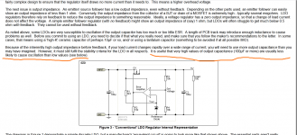
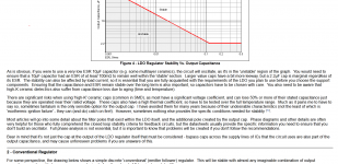
A couple of applications engineers from TI wrote some very nice articles and app notes about instability of low dropout voltage regulators (using the "common emitter" topology). See attachments.
_
_
Attachments
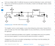
You might find useful this statemnt on ESP site .I often saw LDO's using very high output capacitors who's esr nor esl factors are really low , but you can control them in a real circuit with a little bit of holistic thinking.Sometimes a 10 000uf capacitor works great with an LDO, but at the same time if you are using an LDO with a high Vin-Vout margin everything is safe with almost every capacitor output .
LDO Regulators
Two years ago a i had a small project with a school that asked me to make a small instalation that would show students how you can charge a smartphone using a bike and a dynamo.As it was for students it had to be very descriptive with lots of lights(vu-meters, voltage and current display at all times. I made two types of regulators for the usb carger: one was a 0.5v drop regular LDO chip, the other was a buck boost converter and actually one of the most efficient on the market. Due to the very low output of the bike dynamo it prooved that the series regulator LDO had the same efficiency as the switching circuit, but to make sure that both the LDO and the switching charger would get me the best efficiency all the time no matter how hard the kids were pedalling, i chose a trick shown by a guy whose post you have below. Since then i always try using voltage multipliers in my low power circuits as they also show better filtering right from the start . For a static instalation that you don't need to move pedaling the sealed lead battery regulator was the real deal")
LDO Regulators
Two years ago a i had a small project with a school that asked me to make a small instalation that would show students how you can charge a smartphone using a bike and a dynamo.As it was for students it had to be very descriptive with lots of lights(vu-meters, voltage and current display at all times. I made two types of regulators for the usb carger: one was a 0.5v drop regular LDO chip, the other was a buck boost converter and actually one of the most efficient on the market. Due to the very low output of the bike dynamo it prooved that the series regulator LDO had the same efficiency as the switching circuit, but to make sure that both the LDO and the switching charger would get me the best efficiency all the time no matter how hard the kids were pedalling, i chose a trick shown by a guy whose post you have below. Since then i always try using voltage multipliers in my low power circuits as they also show better filtering right from the start . For a static instalation that you don't need to move pedaling the sealed lead battery regulator was the real deal
Attachments
Last edited:
- Home
- Amplifiers
- Power Supplies
- Are you really fine with IC voltage regulators ?