You could redo the measurements you made earlier by using REW with V/rtHz scale. I also would like to see your LNA noise with input shorted in REW. You can use averaging and 1/48 smoothing to make the graphs neater.
And also LNA shorted with 1k resistor just for verification.
And also LNA shorted with 1k resistor just for verification.
Last edited:
I don't think the reading I obtained above is correct.
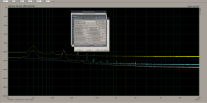
In REW, I shorted the LNA input lead and got a reading of 2.21mV. I was on the V/square root Hz scale, the reading was in the small box on the upper right.
I took 2.21 X1.41 to obtain the +3dB reading of 3.1161mV.
I used an assortment of metal film resistors and the closest I came was 3.17mV with a 68 ohm resistor.
I put that in a resistor noise calculator and obtained the following:
68.0 Ohm resistor at 20.0 °C within 5.0 Hz to 20000.0 Hz frequency band will have :
Noise Spectral Density = 1.049231e-9 V/√Hz or 1.0492 nV/√Hz
I believe this because the LNA is being driven from a 20VAC wall wart. The power supply of the LNA uses half wave rectification, then CRC, then LM317/337 with denoiser.
Your measurement was actually 2.21 uV as 60 dB (1000x) LNA is being used. At REW RTA measurement window, there is “FS sine Vrms” box at top. Put there 0.001 value and voltage readings will be correct. However, this is not relevant for performed relative measurement. 1 nV/Rt Hz is still good. Use multiturn trimmer pot (50 to 100 Ω) to find exact resistor value.

Reasonable power supply noise and ripple shouldn’t affect LNA as they are usually designed with good inherent PSRR. What type of LNA did you build?So now I know the LNA in it's current form has approximately 1nV/√Hz of noise. I believe I can improve that by implementing the dienoiser on the board. That will have to wait until the parts show up.
Now what do I do?
BTW, it’s time for nap at this side of pond.

I have a meeting, but will be back, this is starting to get where I need it to be. I skimmed the post from bohrok2610 and missed the 1000 ohm resistor. I'll do that after the meeting. I did set the "FS sine Vrms" to .001 for the picture above.
How did you get from 1.0492nV to 2.21uV? I'm not following that, understand the 60dB, not the math.
How did you get from 1.0492nV to 2.21uV? I'm not following that, understand the 60dB, not the math.
@tombo 56
LNA is based on the pdf below. Only 3 ZTX951's and resistors added in a ladder for more gain steps up to 60dB. I also used NE 5532 for top opamp and TL071 for servo on bottom.
View attachment Scan20210216162342.pdf
LNA is based on the pdf below. Only 3 ZTX951's and resistors added in a ladder for more gain steps up to 60dB. I also used NE 5532 for top opamp and TL071 for servo on bottom.
View attachment Scan20210216162342.pdf

The ill-behaviour of TI 337s caused oscillations that could be seen by VRDN not reaching regulated voltage. The slightly lower performance in RickRay's measurement was not caused by oscillations. Further measurements are probably needed to find out the real cause.
In all my tests LM337 from TI worked fine with denoiser and also with dienoiser. It shouldn't have any issues, with stability or performance as long as a low ESR output capacitor is used. I used ones with around 50mOhm and worked fine. I could even make it work with a ceramic 1206 capacitor + resistor + small inductor with the dienoser, which pushes the performance of the LM337 even further than the denoiser does.
As long as the circuit has a proper layout and the correct values are used the TI LM337 shouldn't have any issues either with performace nor with stability.
I remember this project using a ESR correcting resistor for the LM337 output capacitor which is not correct. That capacitor should be low ESR, and in my tests around 50mOhm worked fine.
I made a relative measurement in ARTA between the 1k resistor on the input of the LNA and the LNA input shorted. I also made a measurement for the shorted input of the ADC.
While measuring I tried to check, based on the 1k resistor if the 0dB point is acurately set, and it didn't work out that good for the expected 4nV/√Hz. The 0dB point I set based on the alc892 datasheet which states 1.3V max input, so I figured it's rms so I put 3672mV. But replacing that with 1300mV seems to work out pretty close for the 1k resistor, measuring at about -110dB. If the units of measure in ARTA calibration values are the same as the ones shown on the graph then -110dB from 1300mV means around 4.1uV.
I'm not sure if that is a coincidence or not, I'll have to double check this with a measured input signal into the ADC. I will try this when I get to test also with REW.
Even so, I made the measurements both with 1300mV and with 3672mV for 0dB. For the 1300mV the difference between 1k resistor and LNA input grounded came at around 16.42dBV/√Hz, and for the 3672mV for 0dB the difference between the 1k resistor and grounded LNA input came out at about 16.86dBV/√Hz. That means that the LNA noise for 1300mV for 0dB is 0.6nV/√Hz and for the 3672mV for 0dB is 0.57nV/√Hz. I think ARTA just offsets the graph scale for different 0dB but I figured I measure at both 0dB points just to make sure.
I will also try it in REW but I expect the same result, else ARTA would be useless as a piece of software.
So I think the LNA noise should be around the 0.6nV/√Hz mark.
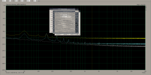
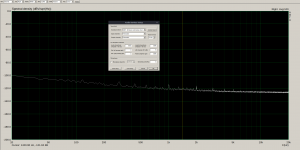
The pictures attached are as follows:
1. 0dB at 1300mV for LNA input to GND.
2. 0dB at 1300mV for 1k resistor across the LNA input.
3. 0dB at 1300mV for ADC input to GND.
4. all previous 3 photos overlayed.
5-8 same thing but with 3672mV for 0dB.
Unless I did something wrong, so feel free to correct me. I've never done this before.
While measuring I tried to check, based on the 1k resistor if the 0dB point is acurately set, and it didn't work out that good for the expected 4nV/√Hz. The 0dB point I set based on the alc892 datasheet which states 1.3V max input, so I figured it's rms so I put 3672mV. But replacing that with 1300mV seems to work out pretty close for the 1k resistor, measuring at about -110dB. If the units of measure in ARTA calibration values are the same as the ones shown on the graph then -110dB from 1300mV means around 4.1uV.
I'm not sure if that is a coincidence or not, I'll have to double check this with a measured input signal into the ADC. I will try this when I get to test also with REW.
Even so, I made the measurements both with 1300mV and with 3672mV for 0dB. For the 1300mV the difference between 1k resistor and LNA input grounded came at around 16.42dBV/√Hz, and for the 3672mV for 0dB the difference between the 1k resistor and grounded LNA input came out at about 16.86dBV/√Hz. That means that the LNA noise for 1300mV for 0dB is 0.6nV/√Hz and for the 3672mV for 0dB is 0.57nV/√Hz. I think ARTA just offsets the graph scale for different 0dB but I figured I measure at both 0dB points just to make sure.
I will also try it in REW but I expect the same result, else ARTA would be useless as a piece of software.
So I think the LNA noise should be around the 0.6nV/√Hz mark.
The pictures attached are as follows:
1. 0dB at 1300mV for LNA input to GND.
2. 0dB at 1300mV for 1k resistor across the LNA input.
3. 0dB at 1300mV for ADC input to GND.
4. all previous 3 photos overlayed.
5-8 same thing but with 3672mV for 0dB.
Unless I did something wrong, so feel free to correct me. I've never done this before.
Attachments
-
 3600mV.png201.6 KB · Views: 68
 -
 3600mV_ADC_input_gnd.png102.3 KB · Views: 64
 -
 3600mV_1k.png101.4 KB · Views: 58
 -
 3600mV_LNA_input_gnd.png102.9 KB · Views: 194
 -
 1300mV.png194.6 KB · Views: 196
 -
 1300mV_ADC_input_gnd.png101.5 KB · Views: 205
 -
 1300mV_1k.png100.7 KB · Views: 194
 -
 1300mV_LNA_input_gnd.png102.2 KB · Views: 204
Last edited:
Also it seems that nobody picked up on the clue I left in this post:
VRDN: bipolar regulator PCB for line level ckts: ±11V to ±20V @ 1.5A with "De-Noiser"
If you check the photos, you'll see the ARTA 0dB point is set at 3.672V, not at 1.3V as I said.
Anyway, if you make the calculation with 0dB as being at 3.67V as it was set in ARTA then -140dB comes out at around 0.36uV, which is right where the denoiser should be as noisefloor.
I think I got confused between Vpp and Vrms when I first set it. The only point when I bumped into this was now with the 1k resistor noise, it didn't correctly translate to what I was expecting using 1.3V instead of 3.67V.
My point, again, is that you can do a lot of relative measurements and check&fix issues without ever knowing absolute values. Especially if you make and measure different versions of LM3x7+de/dienoiser, you start to expect where noisefloor/ripple should be. No need for absolute values.
I have a meeting, but will be back, this is starting to get where I need it to be. I skimmed the post from bohrok2610 and missed the 1000 ohm resistor. I'll do that after the meeting. I did set the "FS sine Vrms" to .001 for the picture above.
How did you get from 1.0492nV to 2.21uV? I'm not following that, understand the 60dB, not the math.
You got a reading of 2.21 mV on the scale relative to the default 1V reference. Real value is 1000x (60 dB) smaller or 2.21 uV. Putting a 1000 x smaller reference voltage corrects REW readings to the real proportion.
In the picture above, I see 9.947 value in the “FS sine Vrms” box? There should be 0.001 value, if 1000x LNA is being used.
With known noise source value at the LNA input, you just adjust REW reading at that value using Focusrite gain control, and your LNA + measurement SW will display real values. It is good to check at several points, including short circuit, with resistors up to 10K. For higher resistor values, LNA input impedance, in parallel with resistor, would affect correct calibration readings.
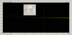
@bohrok2610
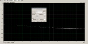
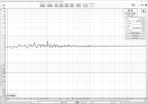
Here is the LNA with a 1k resistor soldered on the input cable.
View attachment 923290
How do I get 4nV of noise from this plot?
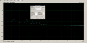
That does not look correct but it is a bit hard to read. You should change the vertical scale to run from 10mV to 100pV.
BTW there is a screen capture tool in Windows 10. No need to take photos.
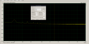
With 1k resistor shorting the LNA input you should see something like this in REW.
Attachments
Last edited:
@tombo 56
LNA is based on the pdf below. Only 3 ZTX951's and resistors added in a ladder for more gain steps up to 60dB. I also used NE 5532 for top opamp and TL071 for servo on bottom.
View attachment 923288
Noise floor about 1 nV/rtHz seems right for this LNA.
Input transistors are connected to the power supply through resistor instead of CCS, so this LNA could benefit from good PS. It could be that current PS with denoisers is good enough. You could spare yourself from unnecessary job by testing LNA using battery PS (2x9V per rail) to see if there is an improvement in noise and 120 Hz ripple.
I got around 0.6nV/√Hz with the 1k resistor measurement.
Sigh...
You should really take some time to learn about noise measurements.
I used the method that this member used here:
https://www.diyaudio.com/forums/equ...-measurement-amp-ikoflexer-3.html#post4874204
Seems like member Scott Wurcer is happy with the result and the way cwtim01 measured it.
Why wouldn't you accept it?
https://www.diyaudio.com/forums/equ...-measurement-amp-ikoflexer-3.html#post4874204
Seems like member Scott Wurcer is happy with the result and the way cwtim01 measured it.
Why wouldn't you accept it?
Sigh...
You should really take some time to learn about noise measurements.
Think it would be productive if I replied with "You should really take some time to learn about how to read measurement graphs" ?
You do realize that the thermal noise of a 1 k resistor at room temperature is 4,07nV/rtHz? If you measure anything below that your measuring equipment (or you logic) has failed.
So you didn't even read my post? I meant the resulting noise of the LNA was 0.6nV/rtHz using the 1k measuring method. The resistor was at 4nV as it should be. I made a complete post with measurements for 1k resistor, and grounded LNA input, and grounded ADC input.
- Home
- Amplifiers
- Power Supplies
- VRDN: bipolar regulator PCB for line level ckts: ±11V to ±20V @ 1.5A with "De-Noiser"