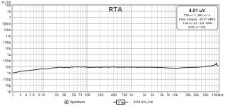
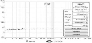
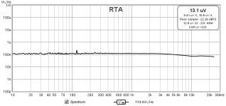
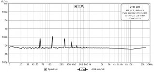
2nd try at VRDN Measurements
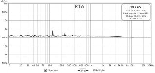
I calibrated my LNA and ADC with a 1K resistor soldered into a BNC connector right at the input of the LNA. Then adjusted the gain on the ADC to get approx. 4uV/square root Hz. 1000 times 4nV/square root Hz.
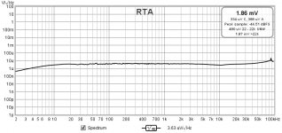
I then attached the VRDN positive rail to the LNA through a coaxial cable terminated with a BNC connector on the LNA end and the wire and shield at the other end.
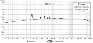
If I am reading this correctly, I divide by 1000 for the LNA and get approx. 20 nV/square root Hz.
Let me know if this is correct and I will measure the negative rail to get a baseline.
After that I can start to make changes and verify if they are helping or hurting.
I can also perform the with and without denoiser tests again.
I calibrated my LNA and ADC with a 1K resistor soldered into a BNC connector right at the input of the LNA. Then adjusted the gain on the ADC to get approx. 4uV/square root Hz. 1000 times 4nV/square root Hz.

I then attached the VRDN positive rail to the LNA through a coaxial cable terminated with a BNC connector on the LNA end and the wire and shield at the other end.

If I am reading this correctly, I divide by 1000 for the LNA and get approx. 20 nV/square root Hz.
Let me know if this is correct and I will measure the negative rail to get a baseline.
After that I can start to make changes and verify if they are helping or hurting.
I can also perform the with and without denoiser tests again.
@tombo56 I calibrated the input level at 1mV, the second I hit enter it changed it to the FS sine Vrms of 1.351. Anything you enter in that calibration box it changes.
Just had a thought, are you hitting the calibration button and opening the other box or just entering 0.001 into the FS sine VRMS box?
Just had a thought, are you hitting the calibration button and opening the other box or just entering 0.001 into the FS sine VRMS box?
Disregard both of the last two sets. The input coaxial broke right at the VRDN where I couldn't see it until I went to take it apart. I'll try again tommorrow.
The calibration pictures are both accurate, so I still would like to know which way is correct.
@tombo56 I calibrated the input level at 1mV, the second I hit enter it changed it to the FS sine Vrms of 1.351. Anything you enter in that calibration box it changes.
Just had a thought, are you hitting the calibration button and opening the other box or just entering 0.001 into the FS sine VRMS box?
Just enter 1 mV value in the box and that's it.
"Calibrate level" button is used, with precise external signal generator, to adjust
reading to the known value at input of measurement gear.
I think I calibrated wrong with the pictures above. Correct me if I'm wrong, I should use the number in the upper right box to calibrate to 4nV with the 1k resistor on the input, right?
Don’t look at that box. There is a total voltage in the specified bandwidth. Just read V/rtHz scale at left. For the1 K resistor, fft graph line should lay at 4 nV/rtHz value (look at 1 kHz frequency and disregard lowest and highest frequency readings due to the shortcomings of the audio interface and LNA). After confirming that, proceed to the VRDN measurement. Expected noise level is below 10 nV/rtHz.
Don’t look at that box. There is a total voltage in the specified bandwidth. Just read V/rtHz scale at left. For the1 K resistor, fft graph line should lay at 4 nV/rtHz value (look at 1 kHz frequency and disregard lowest and highest frequency readings due to the shortcomings of the audio interface and LNA). After confirming that, proceed to the VRDN measurement. Expected noise level is below 10 nV/rtHz.
Yes, with 1k resistor you should get a straight line that lays on the 4nV/rtHz value on vertical scale (see post #352). The plot becomes much more readable if you change the vertical scale to run from e.g. 1uv/rtHz to 100pv/rtHz. You can also set the horizontal scale to run from 10Hz to 30kHz.
I did some more reading last night and this is all starting to make sense. The 4nV/rtHz is the noise at that particular frequency or bin (Noise Spectral Density). The reading in the small box to the upper right is basically the total of the noise over a set bandwidth. By using the resistor noise calculator software, I get the following results:
1000.0 Ohm resistor at 20.0 °C within 22.0 Hz to 22000.0 Hz frequency band will have :
Noise Spectral Density = 4.023618e-9 V/√Hz or 4.0236 nV/√Hz
Noise within desired bandwidth = 5.965005e-7 V or 0.5965 uV
I can either use the graph line and line up 4nV/rtHz or use the number in the small window and use .5965uV.
Either method should be accurate as long as the low and high limits set in the REW software match the readings above.
BTW, I used 22-22k, because REW already shows you that number in the small box at the bottom all the time.
Yes, you can do the "calibration" either way. This is not about being ultra-accurate. But once you have done the calibration do not alter the gain setting before measuring your VRDN.
Next step is to determine why denoiser on negative regulator doesn’t work.
It is not caused by design as design is the same for both positive and negative regulator.
Check that right resistor values are in the right position around denoiser circuit. It is hard to measure them while on board but you can compare color codes to the same positions on the positive regulator board. Check diodes, BJT and capacitor orientation etc. I would also carefully inspect all soldering points or even resolder them using higher soldering iron temperature. Four layer board is capable of sinking a lot of heat.
I've been doing a lot of experiments with the two almost-identical VRDN PCBs, one has ON Semiconductor voltage regulator ICs (LM317, LM337), and the other has Texas Instruments ICs. As noted above, one of the boards oscillated and the other did not, when the trimpots were set for maximum output voltage.
I've received advice and suggestions from member Elvee, who created the De-Noiser, and also from quite a few other diyAudio members, and I'm very thankful for their advice. I tried what people recommended, I tried the opposite of what people recommended, I tried Latin-Square Design Of Experiments protocols, and in fact I even tried mass quantities of circuit simulation runs. Plus ordinary trial and error of course.
Eventually I settled upon the values shown below. Only component VALUES are changing; the circuit topology remains the same and the PCB layout remains the same. A few resistor values change, and a few capacitor values change. I'll work with diyAudio Moderators to update the Schematic and the Detailed Parts List in Post #1 of this thread. The Gerber CAD files do not change and all PCBs made with those Gerber CAD files, can use this update.
I'm calling it "Revision A.2" because the Rev A PCB Gerbers are still good and so are the boards made from those Gerbers.
"ZEROHM" is a jumper wire, a zero ohm resistor. Automatic PCB assembly shops prefer zero-ohm resistors because those can be handled by the same tape-and-reel equipment as all other resistors. Hobbyists building boards manually, can use plain wire jumpers if desired.Code:ID Rev.A Rev.A2 ------------------------ R13 15R ZEROHM C15 6.8N 10N R21 0R47 0R33 R14 15R ZEROHM C16 6.8N 22N R22 0R47 ZEROHM
Mark Johnson already did some changes with Elvee's suggestions and Mark's experimenting. Let's start with those changes and then go from there if there are any issues. I may need to order a few caps.
@tombo56 great suggestions, I will start with making sure everything is in right spot and soldered correctly.
Mark Johnson already did some changes with Elvee's suggestions and Mark's experimenting. Let's start with those changes and then go from there if there are any issues. I may need to order a few caps.
You can first try just replacing R14 with a short. If the negative side oscillates then increase the compensation cap (C16).
Last edited:
LOL, I'm moving this thing back and forth and pretty sure I had a whisker strand of wire short out the secondary winding on the transformer, I noticed something smelling hot. Anyway, if the transformer is still good after it cools down, then I will check that. This happened after I removed the ESR cap, will remeasure that also if the transformer is good.
- Home
- Amplifiers
- Power Supplies
- VRDN: bipolar regulator PCB for line level ckts: ±11V to ±20V @ 1.5A with "De-Noiser"
