I do not understand, silicon is in series with the batteries. I'm doing it wrong?
The mosfet in the diagram is there for the purpose of limiting the inrush current from the battery when the relay contacts close. The inrush is potentially caused by the downstream decoupling caps in the DAC being in a state of discharge.
Because batteries can supply enormous amounts of current to a virtual short circuit, the relay contacts can become welded or arc enough to reduce useful life.
Since the mosfet specified (I actually mistyped the device name), a CSD17312, has only 2 milliohms of resistance on the fully on state, it adds a negligible amount of resistance to the circuit (and in fact is far less than typical relay contact resistance).
The relay allows the battery to "float" and be galvanically isolated from the charging circuitry.
Hope that clarifies things.
Cheers
Whit
Not sure I trust mosfet on-state linearity though. There's a reason they aren't used as relays at the output of amplifiers.
If we are going to go through the effort of making an "ultimate" power supply based upon using parts that we have no measurable evidence to why they are superior then it seems counterproductive to use a "good enough" attitude by throwing a semiconductor in series with the power source.
If we are going to go through the effort of making an "ultimate" power supply based upon using parts that we have no measurable evidence to why they are superior then it seems counterproductive to use a "good enough" attitude by throwing a semiconductor in series with the power source.
Last edited:
Is that meant to be a link? If so it doesn't work.
SQ, I'm an objectivist too. That being said, have you read John Walton's (diyAudio member jackinnj) article in Linear Audio, A Comparative Overview of Power Supply Regulator Designs with Listening Tests? While the various regulators measured differently and, in listening tests, sounded differently, Walton had a difficult time correlating the measurements to the listening tests. It's a fascinating article.
In any event, and FWIW, I prefer the sound of my DAC with the master clock powered by a LiFePO4 battery rather than a regulator.
Not sure I trust mosfet on-state linearity though. There's a reason they aren't used as relays at the output of amplifiers.
If we are going to go through the effort of making an "ultimate" power supply based upon using parts that we have no measurable evidence to why they are superior then it seems counterproductive to use a "good enough" attitude by throwing a semiconductor in series with the power source.
You are quite correct about mosfet use in amplifier outputs. However, that scenario deals with large amounts of dynamic current. The DAC scenario is a relatively static load, typically 100 mA or so (or about 33 ohms equivalent static load on average). The main concern for DACs and jitter-prone clock circuits is power supply noise. In this, batteries are arguably thought to be superior and the series mosfet will not contribute much noise or non-linearity because it's on resistance is very small compared to the load (about .006%).
Everything in engineering is a trade-off. There are lots of ways to skin a cat, I'm just suggesting one possibility.
Cheers
Whit
I disagree. With a low impedance load on the dac output the dynamic current draw is going to be the main source of non-linearity within the output stage.The DAC scenario is a relatively static load
I wouldn't want any possibility of non-linear voltage fluctuations at AVCC since it has no PSRR.
I would simply use an optocoupler to feed a relay for galvanic isolation and a static impedance.
Last edited:
Not bad. I like it.
I still have to wonder why batteries or super capacitors are better than a good regulator though. All 3 of them will be useless @ RF no? The output impedance @ audio frequencies is also similar between them. What makes batteries or super caps superior?
The ESR of batteries or super capacitors is almost zero. My personal guess is: As the following formula, when the ESR is almost zero, the ripple voltage will not increase several times when the current increases.
V=R(ESR)×I
In the case of a regulator, in order to achieve a low ripple voltage, it usually has a higher internal resistance which dynamic performance of music will be lower.
Last edited:
Glad you like it. The CSD17312 seems like a good choice for this because the typical Rdson (with Vgs of 3 volts) is less than 2mOhms, a lot less than typical relay contacts. The Vgsth is only 1.1 volts and it can handle 30 amps. The datasheet is here. Also, it comes in a Q5 SMD package, so not much PCB real estate needed.
Cheers
Whit
@ Whit,
I went trough the datasheet of CSD17312 , seems it's a really good candidate of this kind of application. Thanks for your good eyes.
Regards,
Ian
LifePO4 power supply first prototype PCB
Here is the new update of this weekend.
I assembled the first prototype PCB of my LifePO4 power supply on this weekend. The actual components are more than I estimated. Even on the bottom side of PCB. So, it took me a bit more time doing the SMT job. It becomes pretty heavy after all LifePO4 batteries are mounted.
It has all voltage rails to run a DAC. No need any more additional power supply.
Some small hardware bugs were fixed. Each section was carefully tested and works very well now. The charger can deliver up to 10A of charging current. Maybe I need to reduce it a little bit to make the batteries safer. Some new improvements will also be included and implemented in the second version PCB.
Now I'm still working on the code of the FW. Hopefully I can get it fully functional very soon.
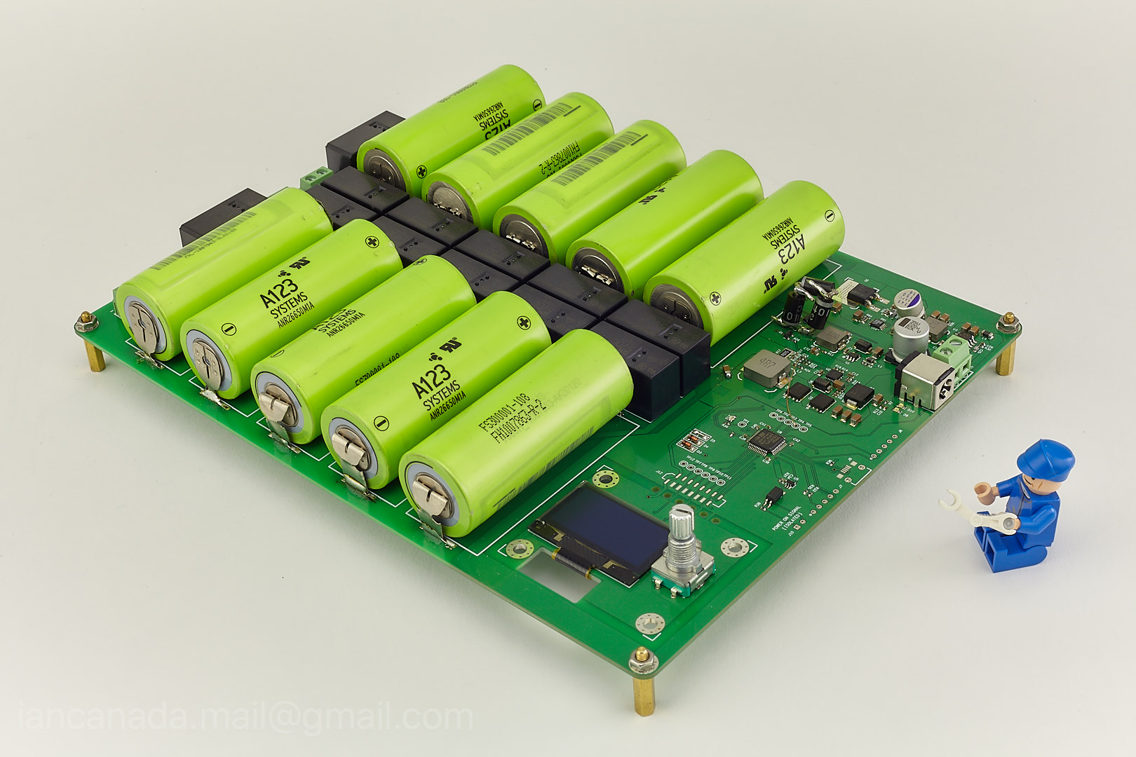
PureLifePO4PowerSupply1 by Ian, on Flickr
Regards,
Ian
Here is the new update of this weekend.
I assembled the first prototype PCB of my LifePO4 power supply on this weekend. The actual components are more than I estimated. Even on the bottom side of PCB. So, it took me a bit more time doing the SMT job. It becomes pretty heavy after all LifePO4 batteries are mounted.
It has all voltage rails to run a DAC. No need any more additional power supply.
Some small hardware bugs were fixed. Each section was carefully tested and works very well now. The charger can deliver up to 10A of charging current. Maybe I need to reduce it a little bit to make the batteries safer. Some new improvements will also be included and implemented in the second version PCB.
Now I'm still working on the code of the FW. Hopefully I can get it fully functional very soon.
PureLifePO4PowerSupply1 by Ian, on Flickr
Regards,
Ian
Attachments
Last edited:
@ Whit,
I went trough the datasheet of CSD17312 , seems it's a really good candidate of this kind of application. Thanks for your good eyes.
Regards,
Ian
Yes - I think it would be good. The best-case ESR for a LiFePO4 cell is about 34 mOhm, depending on state-of-charge and temperature, so the 2 mOhm contribution of the mosfet is not too bad. And if this is regarded as too high, two or more could be paralleled, I would think.
Supercaps (the best ones) are in the same ballpark as far as ESR goes.
As a reference, bear in mind that 1 foot of 24 gauge AWG stranded wire has a resistance of about 25 mOhms at room temperature and the same is true for a 2 inch-long 1mm-wide 1 oz PCB copper trace
") .
.Cheers
Whit
Last edited:
Here is the new update of this weekend.
I assembled the first prototype PCB of my LifePO4 power supply on this weekend. The actual components are more than I estimated. Even on the bottom side of PCB. So, it took me a bit more time doing the SMT job. It becomes pretty heavy after all LifePO4 batteries are mounted.
It has all voltage rails to run a DAC. No need any more additional power supply.
Some small hardware bugs were fixed. Each section was carefully tested and works very well now. The charger can deliver up to 10A of charging current. Maybe I need to reduce it a little bit to make the batteries safer. Some new improvements will also be included and implemented in the second version PCB.
Now I'm still working on the code of the FW. Hopefully I can get it fully functional very soon.
PureLifePO4PowerSupply1 by Ian, on Flickr
Regards,
Ian
That is a serious battery system! And I like the Lego man
So you are up to 12 relays?
Cheers
Whit
Last edited:
It has all voltage rails to run a DAC. No need any more additional power supply.
-----------------------------------------------------------------------------------------
Hi Ian,
Are your suggesting that 3.3Volts is sufficient for powering a Pi3 or a 5 volts piano-dac?
Maybe I should try it myself however....
Ed
-----------------------------------------------------------------------------------------
Hi Ian,
Are your suggesting that 3.3Volts is sufficient for powering a Pi3 or a 5 volts piano-dac?
Maybe I should try it myself however....
Ed
Yes - I think it would be good. The best-case ESR for a LiFePO4 cell is about 34 mOhm, depending on state-of-charge and temperature, so the 2 mOhm contribution of the mosfet is not too bad. And if this is regarded as too high, two or more could be paralleled, I would think.
Supercaps (the best ones) are in the same ballpark as far as ESR goes.
As a reference, bear in mind that 1 foot of 24 gauge AWG stranded wire has a resistance of about 25 mOhms at room temperature and the same is true for a 2 inch-long 1mm-wide 1 oz PCB copper trace
Cheers
Whit
The effective ESR of a good regulator will be in the single digit miliohms in the audio frequency range.The ESR of batteries or super capacitors is almost zero. My personal guess is: As the following formula, when the ESR is almost zero, the ripple voltage will not increase several times when the current increases.
V=R(ESR)×I
In the case of a regulator, in order to achieve a low ripple voltage, it usually has a higher internal resistance which dynamic performance of music will be lower.
I designed a regulator with a theoretical impedance in the nano-pico ohms between 1hz-20khz.
If a battery or super capacitor sounds better, it won't be because of the esr.
It would most likely be due to some sort of purity in the dynamic response.
Which is more reason I am against adding a semiconductor relay in series with the power supply. A non linear impedance can only do harm.
There's a reason they aren't used as relays at the output of amplifiers.
Actually they are. In very high end amps too. As relays generally sound horrible to me, either at amp outputs, or as PS switches, the choice is far from obvious. The mosfets' obvious advantage is the absence of contact deterioration over time.
Really? Haven't heard of anyone doing it.Actually they are. In very high end amps too. As relays generally sound horrible to me, either at amp outputs, or as PS switches, the choice is far from obvious. The mosfets' obvious advantage is the absence of contact deterioration over time.
Of course a mosfet relay can probably be made audibly invisible if it is inside the feedback loop of the amplifier. But there is no such loop when used as a battery relay for AVCC.
It seems foolish to add a non linear impedance to a critical node that has 0 psrr in a circuit that is attempting to push the boundaries of performance of which there is little understanding of the variables for why it is superior in the first place.
Last edited:
It has all voltage rails to run a DAC. No need any more additional power supply.
-----------------------------------------------------------------------------------------
Hi Ian,
Are your suggesting that 3.3Volts is sufficient for powering a Pi3 or a 5 volts piano-dac?
Maybe I should try it myself however....
Ed
@Ed
5V 2A linear rail is designed for RPi which in not isolated.
All other LifePO4 rails are isolated, and you can use them:
Two 3.3V rails for clock and DAC chip
+- 3.3V-13.2V rails for I/V and analog stages
Any LDO after battery will degrade the power supply. You need to remove them. Or you can also bypass them by feeding 3.3V directly rather than 5V.
However, if your DAC chip takes 5V internally, you have to wait for my ultra capacitor power supply which will have pure 5V output.
Regards,
Ian
Last edited:
- Home
- Amplifiers
- Power Supplies
- Develop ultra capacitor power supply and LiFePO4 battery power supply