Hi guys, I'm pretty excited to try UltraBiB with my DAC. Today I started to solder, it's almost done. Besides the PCBs, I also got a set of elements. Everything looks good... except this:

Matt, irregular surface like in some... non-original specimens, I'm not sure about it.
Do you know this brand, can it be safely mounted?
Matt, irregular surface like in some... non-original specimens, I'm not sure about it.
Do you know this brand, can it be safely mounted?
Thank you!Those are Fairchild factory markings.
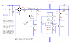
Looking for help with positive version. PCBs are home made, but I cannot get any Vout.
I've attached a schematic with voltages.
All componentes are from Mouser. I used J113 with 20mA Idss and 750R source resistors. Mosfets are IRF9510 and IRF510.
CCS works and I have 1A and that is GOOD! But no Vout and obviously, LED's don't power on.
Trimmer is set to 1.3k ohm, for now, with that values it should be below 12Vout.
Where should I start? Any ideas?
Regards
Attachments

Hi,
check the orientation of Q2 and Q3.
Regards, Matjaz
If I am not mistaken, orientation is correct! I can set 5V - 7V Vout, no more, no less. Should I try different trimmer? 20, 30k?
Regards
Hi,
check the orientation of Q2 and Q3.
Regards, Matjaz
Another update. With trimmer 100K and if I set it to 28K I get 8.2Vout.
Maybe something with JFET and source resistors or? Maybe I can set 12Vout with trimmer set to 100K, but I don't know if this is OK?
Regards
Edit:
If I open the trimmer too much, Vin becomes Vout, so, regulator and CCS, they shut down. Just an info for easier debugging.
Thanks
Last edited:
You can find if the JFETs work for enough local bias current by the voltage drop across each 750R. 1-2mA is normal. Also check Vbe in each BC transistor. You would want 0.55-0.65V. 5K trimmer won't take you as high as expected without enough Vbe across R5 and R6.
If no more DC domain explanation bugs will be discovered, its also possible that using IRF510 as output Mosfet brings very high frequency oscillation. Such a bad AC domain situation could stick the DC adjustment as well. Check the input and output power rails with a scope in AC coupled probe mode. Start from 5mV/50uS vertical/horizontal scale settings.
If no more DC domain explanation bugs will be discovered, its also possible that using IRF510 as output Mosfet brings very high frequency oscillation. Such a bad AC domain situation could stick the DC adjustment as well. Check the input and output power rails with a scope in AC coupled probe mode. Start from 5mV/50uS vertical/horizontal scale settings.
You can find if the JFETs work for enough local bias current by the voltage drop across each 750R. 1-2mA is normal. Also check Vbe in each BC transistor. You would want 0.55-0.65V. 5K trimmer won't take you as high as expected without enough Vbe across R5 and R6.
If no more DC domain explanation bugs will be discovered, its also possible that using IRF510 as output Mosfet brings very high frequency oscillation. Such a bad AC domain situation could stick the DC adjustment as well. Check the input and output power rails with a scope in AC coupled probe mode. Start from 5mV/50uS vertical/horizontal scale settings.
JFETs are at 1.5mA - 1.7mA. 1.16V to 1.3V across 750R. I can lower to 560R if you think it would help?
I think I have IRF640? Would it be better choice than IRF510?
Thanks
No, you don't need to lower the 750R. To the contrary that suggested R degeneration value worked very well for 1-2mA ballpark with the wild IDSS ranging J113 and it biases the BC transistors as expected. IRF640 has better stability prospects for M2 job than IRF510 in this circuit. But do not go for M2 before you establish Q2 Q3 work as expected for Vbe at least.
No, you don't need to lower the 750R. To the contrary that suggested R degeneration value worked very well for 1-2mA ballpark with the wild IDSS ranging J113 and it biases the BC transistors as expected. IRF640 has better stability prospects for M2 job than IRF510 in this circuit. But do not go for M2 before you establish Q2 Q3 work as expected for Vbe at least.
Ok, will do that. I will measure Q2 & Q3 Vbe.
Will report back.
Q2 Q3 Vbe is "printed" across R5 R6. That creates a drop across them and a current to "drive" the Vout trimmer and the two Leds. Vtrim+VLeds+2Vbe = Vout.
I replaced Q2 and Q3 and IRF510 with IRF640 and now I have 12.4Vout, I can regulated output voltage just fine. Thanks for your help. If I will need more help, I will report here.
Thanks
After I tried UltraBiB v1.3 with Soren DAC and noticed the difference not only in sound but also in temperature of polymer caps on the board I started thinking about building PSU (-5V, 5V, and 15V - 50mA max) for TDA1541A with Pedja Rogic approach and Ian FIFO buffer giving this old chip perfect conditions to work and squeeze all that juice I can from this chip.
A few days ago I've purchased 30pcs of J113 and despite that, all of them have exactly the same gm as PF5102, the lowest measured Idss was 12.3mA.
Today someone just told me that 2sk117GR might be a good replacement for PF5102.

The good news is that I found 85pcs of them in my treasure box! Also about 50pcs of BL grade.
2sk117 has a steeper transfer curve than pf5102/j113 but much less than 2sk170 or 2sk163.
I am wondering if this is a good replacement, can I use it without modifying the circuit? I believe I can... can I?")
BTW For choosing the source resistors of J1-J3 I used simple linear interpolation
if for Jfet with Idss of 7.5mA Rs=270 Ohm
and
if for 15mA Rs=560 Ohm
Linear interpolation calculator
then for 20mA we have indeed 750 Ohm, but not sure if this linear dependency is going below 5mA, but I can experiment to achieve Id between 1 and 2mA
A few days ago I've purchased 30pcs of J113 and despite that, all of them have exactly the same gm as PF5102, the lowest measured Idss was 12.3mA.
Today someone just told me that 2sk117GR might be a good replacement for PF5102.
The good news is that I found 85pcs of them in my treasure box! Also about 50pcs of BL grade.
2sk117 has a steeper transfer curve than pf5102/j113 but much less than 2sk170 or 2sk163.
I am wondering if this is a good replacement, can I use it without modifying the circuit? I believe I can... can I?
BTW For choosing the source resistors of J1-J3 I used simple linear interpolation
if for Jfet with Idss of 7.5mA Rs=270 Ohm
and
if for 15mA Rs=560 Ohm
Linear interpolation calculator
then for 20mA we have indeed 750 Ohm, but not sure if this linear dependency is going below 5mA, but I can experiment to achieve Id between 1 and 2mA
Last edited:
2SK117 will work fine circuit wise (I have also tested it during development) but you will have to be creative in assembly regarding the pin order difference to PF or J types. Good thing is it surely has low Vp for J2 (edit, I meant J3) position which comes handy in small Vout adjust range near 5V.
About each JFET type IDSS range vs likely source resistor values needed to moderate mA, I ended up with my published recommendations for this circuit by experiments on the breadboard. I recommend you experiment too.
About each JFET type IDSS range vs likely source resistor values needed to moderate mA, I ended up with my published recommendations for this circuit by experiments on the breadboard. I recommend you experiment too.
Thank you for your help Salas, appreciate your constant support. Yes, I know that 2sk117 and PF5102 have different pinouts as I recently curve traced them , anyway I'm going to design PCB for TDA1541A DAC so will use the correct pins on PCB, also keep the M2 drain and C3 pins as close to the TDA1541A supply pins as possible, to keep Zout at the lowest level.
I hope for 35mA, 45mA, and 50mA (max currents from TDA1541A datasheet) adding an extra 50mA will be enough (6-7 Ohm series resistor), it would not require using large heatsinks
I am going to experiment with the source resistor for 2sk117 and post my findings.
This DAC project isn't going to happen soon as I have two other projects waiting... life's too short!
, anyway I'm going to design PCB for TDA1541A DAC so will use the correct pins on PCB, also keep the M2 drain and C3 pins as close to the TDA1541A supply pins as possible, to keep Zout at the lowest level.I hope for 35mA, 45mA, and 50mA (max currents from TDA1541A datasheet) adding an extra 50mA will be enough (6-7 Ohm series resistor), it would not require using large heatsinks
I am going to experiment with the source resistor for 2sk117 and post my findings.
This DAC project isn't going to happen soon as I have two other projects waiting... life's too short!
- Home
- Amplifiers
- Power Supplies
- Salas SSLV1.3 UltraBiB shunt regulator