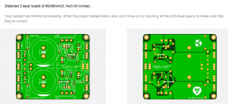
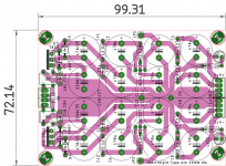
I just loaded the Gerber files in the KiCad gerber viewer and it does appear that the board is smaller than what JLCPCB is detecting. The output transistors along with two drill holes appear as part of the PCB area and then the PCB outline.
Any chance that the originator can upload a fixed version with the correct PCB outline in the edge cuts?
Edit: I have attached an image of the errors in the outline layer where you can see the outline extending beyond the PCB dimensions.
Hi Kozard,
here is modded gerber zip file that doesnt have drill for output which might be causing wrong outline with jlcpcb.
hopefully it will work now.
regards
prasi
Attachments
Prasi, your mastery of PCB layout has inspired v2 of my design. I have attempted to move "all the action" to the output ground connection.
The grounds of C3, C4, R3, R4 have been moved to their own ground plane. The grounds of C1, C2, R1 are run to the output in their own planes (top and bottom). The two only connect at the output faston and surrounding vias.
What do you think?
hi, are there any published gerber files of your multiplier? thanks and good job!
Thank you Mark for your suggestions.
As per the Juma's schematic , the values are 12k Ohm for the R2 and R6.
Also requires a regulated input for the circuit , so the on-board rectifiers + CRC may not be such a good idea.
Regards
Prasi
Hi Prasi, I wanted to ask you if there are gerber files or a specific 3d about these 2 of your pcbs. Thank's for your job. Good day!


My thoughts exactly!We are too lucky that we have you here Prasi!
You are a very generous gentleman.
Best Regards.
Thimios.
 A high class gentleman!
What I wanted to add to this is that I really appreciate collaboration of xrk971, Mark Johnson, Gtose, Juma and others who contributed to this refined and revealing conversation.
I am using Capacitance Multiplier board created here and is available for purchase at pcbway.com. I intend to use Capacitance Multiplier with every amplifier I will ever build. Somewhere I have read that amplifier just modulates power provided from the power supply. I tend to agree with that even though that isn't entirely true. The truth is that a good power supply may make a great amplifier even much greater. And vice-versa: inadequate power supply may totally degrade the sound of otherwise good amplifier.
Thanks guys!
")
I can´t find the schema or a BOM for Juma's Easy-Peasy Capacitance Multiplier
prasi or anyoe else have it?
prasi or anyoe else have it?

Hi Prasi, I wanted to ask you if there are gerber files or a specific 3d about these 2 of your pcbs. Thank's for your job. Good day!
https://ibb.co/x202JYQ
https://ibb.co/LZvdcXz
Hi Taso,
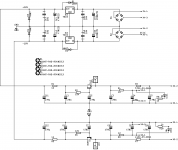
Here is gerbers file for second design. I cant find the other design.
also sch and layout.
I dont think anyone has tested this particular pcb design
regards
prasi
Attachments
Hi, one question:
For this pcb/schematic, if i put all 4 mosfet identical, like irf840 or similar, can i have 4 multiplier for positive voltage?
I have to disconnect/separate the gnd connection?
https://ibb.co/yFQ6hhG
Thanks guys
It will not work as diode orientation is different. best not to try it.
rather you can cut pcb in half and use.
I can´t find the schema or a BOM for Juma's Easy-Peasy Capacitance Multiplier
prasi or anyoe else have it?
Hi Ryssen,
here is a parts list as exported from cad software. so it should help you in choosing appropriate parts.
regards
prasi
Attachments
Hi Taso,
Here is gerbers file for second design. I cant find the other design.
also sch and layout.
I dont think anyone has tested this particular pcb design
regards
prasi
Thanks Prasi, the R are 1/4w?
- Home
- Amplifiers
- Power Supplies
- Juma's Easy-Peasy Capacitance Multiplier