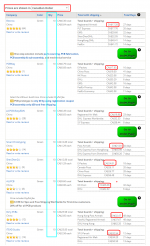
Here are some price quotes I obtained from the website pcbshopper dot com. Shipping to Eastern Canada, prices in Canadian Dollars.
qty = 10 price was CAD 17.28 (including shipping) from the lowest bidder
Click on the white "X" at lower left, to see the image full size and undistorted.
_
qty = 10 price was CAD 17.28 (including shipping) from the lowest bidder
Click on the white "X" at lower left, to see the image full size and undistorted.
_
Attachments
Thanks everyone and Prasi of course for the PCB design.
I’ve had no problem w JLCPCB so I just ordered a small batch of 10.
BR
Eric
I’ve had no problem w JLCPCB so I just ordered a small batch of 10.
BR
Eric
OK...So waiting is done.. I will also place an order tomorrow and ship it to people
prasi-2 nos.
jameshillj-6 nos.
Luke-10 nos.
PCBs would be red masked, 35um cu and 1.6 mm thick from China.
prasi-2 nos.
jameshillj-6 nos.
Luke-10 nos.
PCBs would be red masked, 35um cu and 1.6 mm thick from China.
Hello Eric,
Yes, I have provided a separate gerber file containing 'v-score' layer in the middle in the attached gebers here.
Hello Luke,
I could do a GB if there is more interest (20-30 nos.), pcbs would be in 2.4mm thickness and 70um copper. So here is list
prasi-2 nos.
jameshillj-4 nos.
Luke-2 nos.
Otherwise I can order a batch of 10 pcbs from China and send you couple. Lets wait a day or two to see.
regards
Prasi
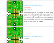
Seems jlcpcb needs the panels to be atleast 7cm x 7cm for it to process v-score . So i have removed the v-score layer in the attached gerbers.
one could manually score it and separate the pcbs if needed.
When i replaced the gerbers , it got approved immediately. see attached image.
Attachments
Last edited:
Prasi, what about laying out another pair horizontally, separated with a v-score. The PCB price at JLC only goes up by $4 or so for 100x120mm and then you get double the boards and reach the minimum size for v-scoring.
Seems jlcpcb needs the panels to be atleast 7cm x 7cm for it to process v-score . So i have removed the v-score layer in the attached gerbers.
one could manually score it and separate the pcbs if needed.
When i replaced the gerbers , it got approved immediately. see attached image.
Hi Prasi
This is strange because I sent your file (91mm x 56mm) to the same PCB house and there was no issue during the review, production was completed today. Have you tried twice?
BR
Eric
Thanks everyone and Prasi of course for the PCB design.
I’ve had no problem w JLCPCB so I just ordered a small batch of 10.
BR
Eric
Hi, Eric
Just curious, do you think you might be able to spare a pair (for both rail)?
Regards,
Hello gtose,
I didn't think of that. Thanks . But I had already ordered. So for others I will do it and post gerbers.
Hi Eric,
I didn't try twice, just removed the vscore line and uploaded the gerbers.
Probably such manual checks at jlcpcb are person dependant , so you got lucky.😉
Regards
Prasi
I didn't think of that. Thanks . But I had already ordered. So for others I will do it and post gerbers.
Hi Eric,
I didn't try twice, just removed the vscore line and uploaded the gerbers.
Probably such manual checks at jlcpcb are person dependant , so you got lucky.😉
Regards
Prasi
I tried a few times with jlcpcb and got no luck too.
I will order some with the updated gerbers.
I will order some with the updated gerbers.
Prasi, what about laying out another pair horizontally, separated with a v-score. The PCB price at JLC only goes up by $4 or so for 100x120mm and then you get double the boards and reach the minimum size for v-scoring.
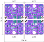
Hello gtose,
Here is 2 side by side layout with v-scoring all around.
regards
Prasi
Attachments
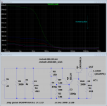
It's pretty instructive to calculate the output impedance (vs frequency) of the two alternatives. ESR and ESL of the Big Old Bohunker Capacitor Bank prevent it from delivering all of the goodness that an ideal perfect "university chalkboard capacitor" would give you, in theory. While the "Capacitance Multiplier" benefits tremendously from high bias Class-A downstream circuits, and from modern power transistors with high fT. Crank the algebra, or run the sim. It'll be fun.
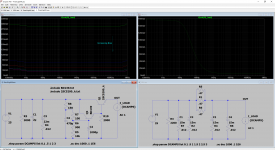
I was curious how the output impedance of this popular CapMX (based on the schematic in #477) compared to the standard PSU used in FirstWatt designs.
Based on the Mark Johnson Happiness Threshold™, the CapMx does great at normal class A power amplifier bias levels (see first attached photo).
If class A output stage is push-pull, let X = 2 * output stage bias current (in amps)
Then I would be happy, personally, if my power supply's output impedance remained below Z ohms, for all frequencies from 10 Hz to 100 kHz. The number Z is calculated thus:Example 1: A class-A amplifier with a constant current source pullup in its output stage, runs at 3.5 amperes of bias. Then Z = 0.5 / 3.5 = 0.14 ohms
- Z = 0.5 / X
Example 2: A class-A amplifier with a push pull output stage, runs at 2.0 amperes of bias. Then Z = 0.5 / 4 = 0.12 ohms.
But of course, my preferences and "happiness threshold" might be different from yours.
Notably, the CapMx far outperforms the CRC below 100 Hz, where the CRC does not meet the Happiness Threshold™. Adding massive amounts of capacitance only shifts the slope slightly to the left: 200mF gets about .12 Ohm at 10 Hz.
Adding another cap on the output of the CapMx seems to offer marginal improvement at higher frequencies, so long as the bias current is reasonable (see second attached photo).
Attachments
Last edited:
Thanks everyone and Prasi of course for the PCB design.
I’ve had no problem w JLCPCB so I just ordered a small batch of 10.
BR
Eric
Well, I should be receiving my PCB within the next 2 weeks, they were ordered on Jan 6 so more than 3 weeks ago (way before the Chinese New Year rush) so it will be 5 weeks total...JLCPCB...never again !!!
PCBWAY is so much better and quicker, it’s a no brainer.
Thanks for the recommendation, at least I gave them a chance...
YMMV
Eric
Last edited:
Well, I should be receiving my PCB within the next 2 weeks, they were ordered on Jan 6 so more than 3 weeks ago (way before the Chinese New Year rush) so it will be 5 weeks total...JLCPCB...never again !!!
PCBWAY is so much better and quicker, it’s a no brainer.
Thanks for the recommendation, at least I gave them a chance...
YMMV
Eric
Hmmm..5 weeks? that's unusual, are you getting it through snail mail or DHL? in my experience JLCPCB is a better one among the bunch. I suspect it may due to the situation in Hong Kong? Most of the stuff coming out of mainland China still have to pass through Hong Kong.
Hmmm..5 weeks? that's unusual, are you getting it through snail mail or DHL? in my experience JLCPCB is a better one among the bunch. I suspect it may due to the situation in Hong Kong? Most of the stuff coming out of mainland China still have to pass through Hong Kong.
It was shipped on Jan.9 by registered air mail.
Hi all - just waiting for my boards from JLCPCB - thanks Prasi. A few quick questions from others experience:
1 How critical are the electrolytic capacitor values? For example, I have a bunch of 2200uf that will fit directly instead of the 1000uf - any disadvantages?
2 Same for the 470uf - any downside to increasing it to say 1000uf?
3 Is there an "optimum" value for the cap that is being "multiplied" (currently one of the 1000uf).
I'm happy to build and test - but without suitable test gear or sim software, I'll be going by ear.
Thanks Adrian
Sorry to lay on more questions...
If you use this CapX for a low line stage with a low draw of 50-200mA is there a better choice for the power transistor than a honking big TIP41/42?
If you use this CapX for a low line stage with a low draw of 50-200mA is there a better choice for the power transistor than a honking big TIP41/42?
Hello Wan,
there was a smd version which xrk used successfully for hpa's in which he used 2sa1837 i think.
regards
prasi
edit: Juma's Easy-Peasy Capacitance Multiplier
he used BD139/140... so works great.
there was a smd version which xrk used successfully for hpa's in which he used 2sa1837 i think.
regards
prasi
edit: Juma's Easy-Peasy Capacitance Multiplier
he used BD139/140... so works great.
Last edited:
- Home
- Amplifiers
- Power Supplies
- Juma's Easy-Peasy Capacitance Multiplier