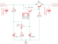
Will I need to use a zener in place of the diode?
I read through this thread a while ago and from what I gathered the voltage and current limits were down to the MOSFETs, afaik the diode is a protection diode, what would be the reason for using zener here?
Does it make sense to add an RC filter after the circuit?
Cap multi> 0.5ohm> 1000uf
Thanks in advance
Cap multi> 0.5ohm> 1000uf
Thanks in advance
See post #715. Putting an RC afterwards will slightly decrease the effectiveness, like putting an RC after a 7812 voltage regulator.
Finally built up one of the gtose, mjohnson, prasi CapMx boards for use in a dual mono Class A amplifier. I’m tired of chasing ground loops with a single transformer/PSU. Hoping two trannies and two of these will be the ticket. I used 22mF for the big caps since I had those laying around. Powered up nicely on the old dim bulb first try. I have it set to max voltage drop right now. With a 22vac transformer I’m getting 27.5V +/-. So about a 3.5V drop after the rectifiers. I’ll see how much it drops when loaded and maybe dial it up a bit. But seems to be working well. Thanks for the great boards gtose, Mark, and Prasi.
Attachments
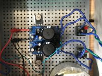
If anyone is curious I used the gerbers from post #597. The boards I got from JLCPCB are on post #614. Also, XRK971 did a build with the same boards around that time with some good documentation of his implementation on his M2X amp. 
Unless those block bridges are Shindengen or similar, you may benefit from using either Shottky diodes or the recent active rectifiers system, particularly after going to the trouble of a 'dual-mono' design.
… just saying, as they say!
… just saying, as they say!
Hello jw,
Nice... Hope everything works out with ground loops.
As a next step, you could also try on with lt4320 recttifiers, just saying
Nice... Hope everything works out with ground loops.
As a next step, you could also try on with lt4320 recttifiers, just saying
Thanks for the suggestion James and Prasi. As Wayne Colburn would say, it’s what we had on the shelf. 😀 I’ll have to give those a try. I have parts for a pair of SLB’s but this was more of a quick, budget experiment for a chassis where I’ll be swapping amps out on a regular basis. And I might use those SLB parts for a pair of ABBB’s instead. They aren’t cheap! 😉
Is this board you all are using good for various headphone amps? Cuz Im searching for psu board to power headphone amps.
Nenad88, that would be the smaller CapMx board. I made up a batch of those as well and have used them for various applications (BA3 PSU, Wayne’s linestage psu) Just keep in mind they aren’t a regulated supply so if you need say, exactly 24v all the time this might not be the PSU for you. But I can attest it is a small and quiet PSU for my applications so far. See posts 626 and 650 for more info on that one.
nenad88. Not entirely. My understanding is you can dial it in within a few volts of your target with the trim pots, but the less voltage you dial down, the less ripple reduction you get. Your target voltage comes from the transformer. I'm shooting for 24V in a Class A amp. Running it with a 22vac transformer I have it dialed as far down as the trim pots will take it. That gives me 27.5V. With a Class A load it should get me closer to 24V. But in the end a 20vac transformer may be what I really need. Well see... So long story short, you can have any voltage you want, theoretically, depending on the transformer. Not to take into account the voltage restrictions imposed by the caps you use or the transistors, etc. That's next level.
One thing I'd suggest when you're first setting these 'simple' filters up is to run them at the current that you'll end up using the supply with via a 'dummy load' and make sure everything is functioning okay.
I have power resistors mounted on heatsinks for this and as I'm often playing with the F series amps, I generally use 16R power resistor or for other current testing loads, a bunch of wire wounds in // and dump them in a non-metal jug or container - you can leave the supply 'on soak' for awhile and get those parts "all settled in"
For example, 6 x 100R 10W resistors wired in parallel = about 16R ohm load and @ 24 volts = about 1.5A = about 50W heat and is enough to get them quite hot!)
Also something that doesn't often get mentioned (and is argued about quite a lot!) but the capacitors in the filter are just like any other component in that they have their own sound - for example, most Nichicons will sound different to most Panasonics and will sound different to Epcos …. you get the idea, yes?
On some systems, the difference isn't noticeable but in others, it's quite significant - on headamps, it's unmistakable - the Cap multiplier circuits generally emphasize the differences.
… all the best
Fired the CapMx up with 16R on each rail tonight on a variac. Brought it up slow just in case. With the 16R load I got 24.5V on each rail. Just about perfect!
nenad88. Not entirely. My understanding is you can dial it in within a few volts of your target with the trim pots, but the less voltage you dial down, the less ripple reduction you get. Your target voltage comes from the transformer. I'm shooting for 24V in a Class A amp. Running it with a 22vac transformer I have it dialed as far down as the trim pots will take it. That gives me 27.5V. With a Class A load it should get me closer to 24V. But in the end a 20vac transformer may be what I really need. Well see... So long story short, you can have any voltage you want, theoretically, depending on the transformer. Not to take into account the voltage restrictions imposed by the caps you use or the transistors, etc. That's next level.
I understand now, but that is not good solution for my needs.
Hope you find what you’re looking for nenad88.
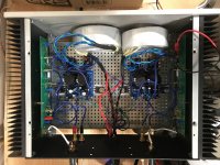
Regarding the boards I’m using I now have both channels up and running. Please disregard the transformer positioning right now. Final positioning and mounting is still in progress. With everything running through efficient speakers (0.53x mini-k’s with dual 3fe25’s) this is the quietest amp I have built this far. I can say this. For an affordable Class A PSU build I don’t think you can beat these boards.
Regarding the boards I’m using I now have both channels up and running. Please disregard the transformer positioning right now. Final positioning and mounting is still in progress. With everything running through efficient speakers (0.53x mini-k’s with dual 3fe25’s) this is the quietest amp I have built this far. I can say this. For an affordable Class A PSU build I don’t think you can beat these boards.
Attachments
Last edited:
- Home
- Amplifiers
- Power Supplies
- Juma's Easy-Peasy Capacitance Multiplier