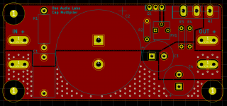
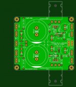
Prasi, your mastery of PCB layout has inspired v2 of my design. I have attempted to move "all the action" to the output ground connection.
The grounds of C3, C4, R3, R4 have been moved to their own ground plane. The grounds of C1, C2, R1 are run to the output in their own planes (top and bottom). The two only connect at the output faston and surrounding vias.
What do you think?
The grounds of C3, C4, R3, R4 have been moved to their own ground plane. The grounds of C1, C2, R1 are run to the output in their own planes (top and bottom). The two only connect at the output faston and surrounding vias.
What do you think?
Attachments

gtose,
That's looking fantastic now. Congratulations and all the best for your build and test. Do post once you complete the testing.
regards
Prasi
That's looking fantastic now. Congratulations and all the best for your build and test. Do post once you complete the testing.
regards
Prasi
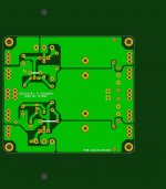
gtose, if you decided to rotate capacitor C4 by 90 degrees, clockwise, you could get much better continuity on the green plane. The green signal track between C4 and the potentiometer, would not interfere with the green plane as much.
Also you might consider adding the two white triangles shown below, onto the green layer.
Also you might consider adding the two white triangles shown below, onto the green layer.
Attachments
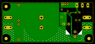
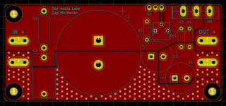
Mark, great suggestion! I've implemented this in version 3 below. I've also reduced the keepout size around the m3 mounting holes to get more width on the input ground plane on the top layer.
Attachments

DigiKey BOM: Index - My Digi-Key
I'm asked to log in to DigiKey, but I don't have an account. Could someone please post the BOM here?
Thanks 🙂
.
Skylar88, the CSV BOM is below.
Code:
"Manufacturer Part Number","Manufacturer","Digi-Key Part Number","Customer Reference","Quantity","Unit Price","Extended Price","Quantity Available","Description"
"BFC237321225","Vishay BC Components","BC1767-ND","C1","1","3.12000","$3.12","672","CAP FILM 2.2UF 10% 100VDC RADIAL"
"SLPX223M035H4P3","Cornell Dubilier Electronics (CDE)","338-1598-ND","C2","1","4.59000","$4.59","688","CAP ALUM 22000UF 20% 35V SNAP"
"BD13910S","ON Semiconductor","BD13910S-ND","Q1","1","0.49000","$0.49","1322","TRANS NPN 80V 1.5A TO-126"
"2SC5200RTU","ON Semiconductor","2SC5200RTU-ND","Q2","1","3.42000","$3.42","483","TRANS NPN 250V 17A TO264"
"EEU-FC1H471","Panasonic Electronic Components","P10328-ND","C3","1","1.04000","$1.04","17034","CAP ALUM 470UF 20% 50V RADIAL"
"ERG-2SJ302","Panasonic Electronic Components","P3.0KW-2BK-ND","R1","1","0.36000","$0.36","9599","RES 3K OHM 2W 5% AXIAL"
"MBB02070C1002FRP00","Vishay BC Components","BC10.0KZCT-ND","R3","1","0.30000","$0.30","48466","RES 10K OHM 0.6W 1% AXIAL"
"MBB02070C1500FCT00","Vishay BC Components","BC3614CT-ND","R2","1","0.30000","$0.30","89383","RES 150 OHM 0.6W 1% AXIAL"
"MBB02070C2001FCT00","Vishay BC Components","BC3653CT-ND","R4","1","0.30000","$0.30","18973","RES 2K OHM 0.6W 1% AXIAL"
"3362P-1-102LF","Bourns Inc.","3362P-102LF-ND","RV1","1","1.02000","$1.02","4415","TRIMMER 1K OHM 0.5W PC PIN TOP"
"63824-1","TE Connectivity AMP Connectors","A29938CT-ND","J1-4","4","0.13000","$0.52","33420","CONN QC TAB 0.250 SOLDER"
"EEU-FC1V102","Panasonic Electronic Components","P10305-ND","C4","1","1.04000","$1.04","19870","CAP ALUM 1000UF 20% 35V RADIAL"Skylar88, the CSV BOM is below.
Thanks gtose. Works perfectly as a CSV.

.
@Prasi
Call me OCD, but I am rather going to be putting in at least 50V, but most likely 63V caps, instead of 35V ones. My Class A amps have 28V power rails. Also, I am thinking of extending the front end of the board, and putting in two 10kuF caps per rail. This would end up taking up an additional 40mm length wise, but cost me 30% less for the caps. The 22kuF are pricey here in SA. Your thoughts/comments on this please, Prashant.
Regards, Kevin
Last edited:
Hello Kevin,@Prasi
Call me OCD, but I am rather going to be putting in at least 50V, but most likely 63V caps, instead of 35V ones. My Class A amps have 28V power rails. Also, I am thinking of extending the front end of the board, and putting in two 10kuF caps per rail. This would end up taking up an additional 40mm length wise, but cost me 30% less for the caps. The 22kuF are pricey here in SA. Your thoughts/comments on this please, Prashant.
Regards, Kevin
There is GB ongoing being done by a member meanman1964 with PMI/Mr. Evil Cap MX that uses 2 caps per rail. I think that would suit your requirements.
Check out the GB section.
regards
Prasi
Hello kevin,@Prasi
Call me OCD, but I am rather going to be putting in at least 50V, but most likely 63V caps, instead of 35V ones. My Class A amps have 28V power rails. Also, I am thinking of extending the front end of the board, and putting in two 10kuF caps per rail. This would end up taking up an additional 40mm length wise, but cost me 30% less for the caps. The 22kuF are pricey here in SA. Your thoughts/comments on this please, Prashant.
Regards, Kevin
I have been thinking about your suggestion.....Yes adding another cap on the input side is good, but I think I asked this before, would adding an output cap be better? SOmething like a quality 4700uF perhaps?
regards
Prasi
Yes, its a 15mm pitch alright, plus now I have put some options for 5mm and 10mm just in case someone wants to use something else.
you can order boards yourself. attached are the gerbs and stuffing guide , also pdfs in case someone wants to etch at home.
Let me know if you have any problems with boardhouse with these gerbers, I can clarify / use older method. I have now moved over to eagle 9.0.0, pcbway didnt like those 9.0.0 gerbers initially. Now its settled with them 😉.
Top plane is a ground plane thats only connected at output.
regards
Prasi
edit: logos are on the bottom silk, so don't affect the functionality or beauty of top silk😀
The gerber zip file in the quoted post above is missing the drill file. Sorry for the omission. It was a mistake. I just came to know about this from xrk.
The correct gerbers are attached herewith. The diy pdf files in the quoted post are ok.
regards
Prasi
Attachments
Thanks Prasi. You're a legend!
Question: What thickness copper is advisable? 2oz adds US$15.50 to the US$ 24.76 price for 1oz (minimum 5 boards) at my favorite board house; seeedstudio.com
3oz adds a whopping US$172.00.
Their Gerber viewer reads your files perfectly, btw. See below.
.
Question: What thickness copper is advisable? 2oz adds US$15.50 to the US$ 24.76 price for 1oz (minimum 5 boards) at my favorite board house; seeedstudio.com
3oz adds a whopping US$172.00.
Their Gerber viewer reads your files perfectly, btw. See below.
.
Attachments
Last edited:
I think xrk is getting some made. If you need only 2, you can save on cost, provided he is willing share his stash.
I think just 15usd for double the copper must be tempting😀.
one needs to tell the boardhouse guys to ignore everything outside the board outline.
Its a common issue with auto detection of sizes being used by boardhouses.
pcbway has a great service in this regard.
I think just 15usd for double the copper must be tempting😀.
one needs to tell the boardhouse guys to ignore everything outside the board outline.
Its a common issue with auto detection of sizes being used by boardhouses.
pcbway has a great service in this regard.
Last edited:
I think just 15usd for double the copper must be tempting😀.
Using the correct board size enables one to make use of the special price for small boards, making the difference much more than 15US$ for 2oz.
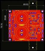
To put my question about copper thickness into perspective: Both Seeedstudio and PCBWay offer a special price for boards up to 100mm x 100mm with 1oz copper. It’s very tempting to go with 1oz, but will it be thick enough for this application?
See the table below. 2oz is almost 10 times the price of 1oz!
Code:
1[FONT="inherit"]oz copper:
[/FONT][FONT="inherit"]   5 boards - $5       10 boards - $5[/FONT]

[FONT="inherit"]2oz copper:
5 boards - $40 10 boards - $49[/FONT]Is that really necessary, or can one get away with 1oz and 1.6mm? (keep in mind I don't pay in US$)
.
1A/mm 1oz.
V+ and V- power planes duplicated on top side and you‘ve 2 oz.
But I suppose too late for modification?
2 cents.
JP
V+ and V- power planes duplicated on top side and you‘ve 2 oz.
But I suppose too late for modification?
2 cents.
JP
well skylar, it's your decision based on cost.
For cheaper options,
PCBShopper – A Price Comparison Site for Printed Circuit Boards
For cheaper options,
PCBShopper – A Price Comparison Site for Printed Circuit Boards
no, I am not going to duplicate the power plane on top. I like the PCB just as is with a contiguous ground plane on top layer. See Mark Johnson's ring not PCB😉.
- Home
- Amplifiers
- Power Supplies
- Juma's Easy-Peasy Capacitance Multiplier