Either ground the sinks with a wire (from a sink's mounting pin pad to zero) and insulate the Mosfets or you don't and you go for the less thermal transfer resistance. When there is no indication of extra output noise on a scope between those two states better go for less thermal resistance. Normally there is no such problem unless a build is full of difficult interference. Nonetheless it would be the same noise situation if with just insulation but the sinks are still floating.
You should measure your J1's IDSS first so to make an informed decision on RR value from the guide's options
http://www.diyaudio.com/forums/pass-labs/141162-2sk170-matching.html
http://www.diyaudio.com/forums/pass-labs/141162-2sk170-matching.html
Hi Tiofrancotirador, thanks, so you use then a second Mundorf ag+ on a C2 place? Nice to know, beacuse of great footprint in this place and more affordable too. I will give a try on this.
Hi, today I compare Mundorf Mlytic Ag+ 1000 uF. against my reference 100uF+47uF+4,7uF+0.01uF in very sensible C2 position. And winner is Mundorf as Francotirador stated, by a wide margin, my previous setup was cheaper, but sterile in comparison.
My Mundorf (not fully broken-in to confirm) is still in need for a bypass, I use by now, a NOS Oil Cap. 4,7uF, to enhance middle frecuencies.
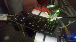
Unfortunatelly from my tests leds are better than lm329. Lm329 seems to generate more hf noise. To get 8V I would go 3 green with highest drop, one 1N4148 and jfet with highest idss.
Hi thanks Tiofrancotirador, it seems another great tip here, I confirm is a wonderful enhancement over Lm329 in my 8v. setup. I suppose also for 12v. power supplies is also possible with more and more leds.
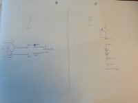
Here is the drawing for correct wiring:
I possibly can post pics from my build if needed.
Please do post your build, mine is on test stage only, I wired it as in your drawing, leds going from IN+ to OUT-.
Attachments
Hello Salas,
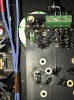
I just set the CSS to 600mA via 1ohm R1, output 8,43V, and ~460mA load with a 18ohm dummy, and I am very please to find out that I can easily put my hand on the sink's.
My question is: if I want to achive 10V and 1,22A CSS with a 0,5ohm R1, my only worryes should be the M1 and M2 temperature?
Thank you !
Hello Salas,
I just set the CSS to 600mA via 1ohm R1, output 8,43V, and ~460mA load with a 18ohm dummy, and I am very please to find out that I can easily put my hand on the sink's.
My question is: if I want to achive 10V and 1,22A CSS with a 0,5ohm R1, my only worryes should be the M1 and M2 temperature?
Thank you !
No only heat, but also you would have use different mosfet with higher current capabilities like FQP3P20.
Hi thanks Tiofrancotirador, it seems another great tip here, I confirm is a wonderful enhancement over Lm329 in my 8v. setup. I suppose also for 12v. power supplies is also possible with more and more leds.
You can go higher with voltage yes, but you have to watch out for the heat if you stay with high CSS as welll. Standard heatsinks may not be efficient in that case.
No only heat, but also you would have use different mosfet with higher current capabilities like FQP3P20.
Hello,
I am already usind FQP3N50C and FQP3P20
EDIT: and 6399BG from Farnell sink's
Last edited:
You can go higher with voltage yes, but you have to watch out for the heat if you stay with high CSS as welll. Standard heatsinks may not be efficient in that case.
Thanks confirmation , my need is 12,8v. for a low power Class T Tripath chip amp. I wants to replace a low current BIB supply, so suppose same standard heatsinks also using Ref-D.
Please do post your build, mine is on test stage only, I wired it as in your drawing, leds going from IN+ to OUT-.
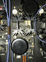
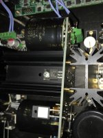
There you go. Salas Ref D Mundorf 4 pin of Vref.
Attachments
There you go. Salas Ref D Mundorf 4 pin of Vref.
I got it, the trick is reverse, everything over the place to the back side!
Is a relief, not that difficult, tomorrow I will arrange mine, thanks!
I will buy soon 4 more 1000uF. Mlytic caps. for my remaining power supplies. Also for digital ones.
I got it, the trick is reverse, everything over the place to the back side!
Is a relief, not that difficult, tomorrow I will arrange mine, thanks!
I will buy soon 4 more 1000uF. Mlytic caps. for my remaining power supplies. Also for digital ones.
For digital, OSCONS wasn't better for C2?
@TioFrancotirador what capacitor did you used for C1?
It would be any benefit to use a larger Mundorf for CM, like 15000uF or 22000uF?
Could you guys please confirm the schematic attached is right for connecting the Mundorfs?
Attachments
There you go. Salas Ref D Mundorf 4 pin of Vref.
TioFrancotirador, if I'm not mistaken you are using your various Ref-Ds to power a DAM1021, right?
If so, would you mind explaining in detail how and where you connect to the dac? I'm confused about the various alternative connection points on the DAM1021. J1, J2 or even powering the clock directly.
I only use the raw output and have removed the opamps on my rev. 1 board. So I'm beginning to think that it might be sufficient to feed the dac with 5V at J1 (at the moment I'm feeding it 12V at J1 and 3.3V at the isolator J3).
Sorry if this is too off topic.
For digital, OSCONS wasn't better for C2?
It would be any benefit to use a larger Mundorf for CM, like 15000uF or 22000uF?
Could you guys please confirm the schematic attached is right for connecting the Mundorfs?
I founded the same picky behavior, in digital as it was in analog ever I adjusted something, capacitirs bypasses, wires dielectrics, etc. BUT still not tried Mundorf in 3,3v. clock supply to conirm against my existing Nichicon KZ.
Concerning the capacitance increase question, I don't know techincal reason, but I experienced serious performance decrease going over 6800uF. in CM.
Schemantic seems right, isn't?
Mundorf in C2 position should offer a better sound, but if we are talking about digital, that should't matter, that's way I was asking about OSCONs. I think TioFrancotirador use polimer in C2 for digital.
BTW TioFrancotirador, you use Mundorf in CM possition for digital as well? I am asking that because they are quite expenssive and I want to reduce the number of them (only for analgogic I preffer )
)
The draw nr. I is 100% correct as I found the same wiring in other places as well, but in the drawing nr. II, my logic say that out - and in - should be swaped
BTW TioFrancotirador, you use Mundorf in CM possition for digital as well? I am asking that because they are quite expenssive and I want to reduce the number of them (only for analgogic I preffer
) .
Schemantic seems right, isn't?
The draw nr. I is 100% correct as I found the same wiring in other places as well, but in the drawing nr. II, my logic say that out - and in - should be swaped
- Home
- Amplifiers
- Power Supplies
- Reflektor-D builds