The draw nr. I is 100% correct as I found the same wiring in other places as well, but in the drawing nr. II, my logic say that out - and in - should be swaped 😕[/QUOTE]
My vote is for wiring as in draw II. Yours suggestad also must work, so definately, tomorrow I wire that way also and compare wich one, if any, sounds better.
Now is on play great football match Barca-PSG on ChampionsLeague!
My vote is for wiring as in draw II. Yours suggestad also must work, so definately, tomorrow I wire that way also and compare wich one, if any, sounds better.
Now is on play great football match Barca-PSG on ChampionsLeague!
For digital, OSCONS wasn't better for C2?
@TioFrancotirador what capacitor did you used for C1?
It would be any benefit to use a larger Mundorf for CM, like 15000uF or 22000uF?
Could you guys please confirm the schematic attached is right for connecting the Mundorfs?
Hi,
C2 - for now I use FPCAP for digital, however I am wonder how it compares to Mundor 4 pin
C1- Mundorf EVO Oil 0,1uF, however I did not find this capacitor to be much of importance
CM - there is the post in this forum, where Salas explained to me how to calculated the value. Basically it depends on Vin, Vout, Load and line frequency. There is formula to calculate that.
Schematic attached - that is the way that I have it connected and it works.
I power Vref directly with two Ref Ds -/+@3,8V.TioFrancotirador, if I'm not mistaken you are using your various Ref-Ds to power a DAM1021, right?
If so, would you mind explaining in detail how and where you connect to the dac? I'm confused about the various alternative connection points on the DAM1021. J1, J2 or even powering the clock directly.
I only use the raw output and have removed the opamps on my rev. 1 board. So I'm beginning to think that it might be sufficient to feed the dac with 5V at J1 (at the moment I'm feeding it 12V at J1 and 3.3V at the isolator J3).
Sorry if this is too off topic.
Clock,isolator,toslink is powered by Ref D@3.3V.
FPGA is powered by Belleson 1,2V.
USB-XMOS is powered by another Ref D@3.3V.
As previously said I am wonder how mundor 4 pin in C2 position compares to FPCAP poyler for powering digital - i did not compared that.Mundorf in C2 position should offer a better sound, but if we are talking about digital, that should't matter, that's way I was asking about OSCONs. I think TioFrancotirador use polimer in C2 for digital.
BTW TioFrancotirador, you use Mundorf in CM possition for digital as well? I am asking that because they are quite expenssive and I want to reduce the number of them (only for analgogic I preffer 😀 )
The draw nr. I is 100% correct as I found the same wiring in other places as well, but in the drawing nr. II, my logic say that out - and in - should be swaped 😕
I have wired my ref ds like in drawing I and II. Maybe swapping -in and -out in drawing II, would work too - I did not tried that, so I do not know.
Hi stefan yes, I compared two wirings just right now, leds going from In+ to In- as your logic suggest, is way preferable. Going back to wiring In+ to Out- was.. how to tell... like reverse the phase on mains power supply. It's a loss on focusing, bass extension and overall coherence.
I am also very happy to discover, wiring your way, no need for my bulky 4,7uF Oil capacitor bypass. (in fact it worsens the sound a lot!!!)
I am also very happy to discover, wiring your way, no need for my bulky 4,7uF Oil capacitor bypass. (in fact it worsens the sound a lot!!!)
Glad you found stefan wiring to better according to your subjective opinion.Hi stefan yes, I compared two wirings just right now, leds going from In+ to In- as your logic suggest, is way preferable. Going back to wiring In+ to Out- was.. how to tell... like reverse the phase on mains power supply. It's a loss on focusing, bass extension and overall coherence.
I am also very happy to discover, wiring your way, no need for my bulky 4,7uF Oil capacitor bypass. (in fact it worsens the sound a lot!!!)
Were did you put 4,7uF? between -in and +in or -out and +out? Can you try both options and report results? I wonder if that matters here.
BTW can you try putting leds between -out and +out and see if this works?Hi stefan yes, I compared two wirings just right now, leds going from In+ to In- as your logic suggest, is way preferable. Going back to wiring In+ to Out- was.. how to tell... like reverse the phase on mains power supply. It's a loss on focusing, bass extension and overall coherence.
I am also very happy to discover, wiring your way, no need for my bulky 4,7uF Oil capacitor bypass. (in fact it worsens the sound a lot!!!)
BTW can you try putting leds between -out and +out and see if this works?
Jajaa, yes! that's remaining essay, I know, well you are right, great difference in sound today encourages me follow on and squeeze further the mundorf to the end.
Concerning the 4,7uF. bypass connexion:
I don't remember from yesterday, wait! I think IN+/IN- (I posted a photo to check out for sure) and connected today at IN+/OUT- , by no reason, just being practical places (being a bypass..), It worsens the sound a lot, really lot in fact, and then quick remove one lead (alligator one) to disconnect.
Yesterday with your wiring, it was opposite, adds some pleasant loudness with more pros than cons, so I left it, altough I knew it was not definitive.
Hi,
C2 - for now I use FPCAP for digital, however I am wonder how it compares to Mundor 4 pin
Hello,
In two weeks from now I will go to school and use theire avaible equipment(very good stuff) to measure noise and hopefully output impedance using different cap on CM, C1, C2 and LM329 vs LED's, choke input, etc.. These measurements will be relevant only for digital side, where the quality of sound isn't relative. Unfortunately I will do the same test with Mundorf later on because now my budget is limited 🙁
If anyone have other sugestions of what measurments should I do or parts to add/skipp, I am open to suggestions.
Regard the choke input: some users report that using a 1,5mH choke will reduce noise and even guide to buy them for a few bucks. In simulation this will work, but in reality it don't, in fact they even add noise 🙂 The problem is that these tipes of choke are not made for DC, their are made for AC or pulse DC, and ussing them in continuous DC will made them to saturate and to buzz. Using a dedicated DC choke that are more big and expensive, should do the trick, unfortunately I don't have any of them to make tests, but I will put a simple and a common mode 1,5mH choke before the rectifiers to see if it will help.
Salas, do your forumula for calculating the CM size will be good for Mundorf 4 pins too? They have different dielectric than an ordinary electrolytic cap, and I am wonder if the uF value should be different.
Last edited:
Regarding rectification ripple frequencies 100-120Hz the textbook formulas for CM's value vs its current sufficiency and drop voltage margin in expected loading range are universal. C2's listed value has to do with sufficient VLF (1/F) noise filtering of the Vref components which can be important to clocks and the like. Pre-filtering with proper DC current rated choke can help in much higher frequencies than ripple's where the practical constant current sources become transparent to rectification's byproducts and other possible interference.
BTW can you try putting leds between -out and +out and see if this works?
I placed the leds between OUT pins, and sadly the board become malfunction, maybe I power on before leds were in place, not sure, but no way to fix by now. I tested the semis, mosfets, resistors, leds... It seems when power on it's ok. but after 4 or 5 seconds leds dim off smothly to dead.
I placed the leds between OUT pins, and sadly the board become malfunction, maybe I power on before leds were in place, not sure, but no way to fix by now. I tested the semis, mosfets, resistors, leds... It seems when power on it's ok. but after 4 or 5 seconds leds dim off smothly to dead.
Sorry to hear that 🙁
I have tried leds inbetween -in and +in. In my case I did not hear any differences in comparison to leds inbetween (+in and -out).
One thing is certain however: mundorf 4 pin is the best for C2.
Either ground the sinks with a wire (from a sink's mounting pin pad to zero) and insulate the Mosfets or you don't and you go for the less thermal transfer resistance. When there is no indication of extra output noise on a scope between those two states better go for less thermal resistance. Normally there is no such problem unless a build is full of difficult interference. Nonetheless it would be the same noise situation if with just insulation but the sinks are still floating.
Hello Salas,
I have done measurements using both methods, and the difference is only ~3-4 degree. I am missing something or it is normal?
Also if you are so kind to tell me the formula for calculating the CM, that will be great! I don't find it on this topic, and on the internet are different from website to website.
Attachments
CM formula:Hello Salas,
I have done measurements using both methods, and the difference is only ~3-4 degree. I am missing something or it is normal?
Also if you are so kind to tell me the formula for calculating the CM, that will be great! I don't find it on this topic, and on the internet are different from website to website.
http://www.diyaudio.com/forums/power-supplies/261031-reflektor-d-builds-82.html#post4818424
Post 815 on this thread.
I fixed the issue, and proceed to test the Mundorf 4 pin. And I get rewarding to my efforts, I tested diodes position back and forth several times, to prevent mistake, and I can stand now, it's a nice upgrade placing diodes from OUT+ to OUT-, over last try, between IN+ and IN-.
I don't feel in need for bypass to such a kind of capacitor. My god!
I don't feel in need for bypass to such a kind of capacitor. My god!
An externally hosted image should be here but it was not working when we last tested it.
I fixed the issue, and proceed to test the Mundorf 4 pin. And I get rewarding to my efforts, I tested diodes position back and forth several times, to prevent mistake, and I can stand now, it's a nice upgrade placing diodes from OUT+ to OUT-, over last try, between IN+ and IN-.
I don't feel in need for bypass to such a kind of capacitor. My god!
An externally hosted image should be here but it was not working when we last tested it.
How do you describe the difference in sound?
You still have one more combination to go 🙂
attach your pic.
I uploaded yesterday the pic to my 'Google Drive' and generate a link, maybe not works from there, so now new link is from my 'Microsoft Onedrive'. Uf.. what a nightmare!
An externally hosted image should be here but it was not working when we last tested it.
Go to advanced answer and manage attachments to upload it. First resize to medium analysis and few hundred kilobytes if an original picture is huge. 
Go to advanced answer and manage attachments to upload it. First resize to medium analysis and few hundred kilobytes if an original picture is huge.
Thanks advice Salas, I am into 'Reply to Thread' and loocking below, 'Additional Options', then 'Attach Files', then 'Manage Attachments' so I think I got.
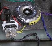
I placed a new pic now, it's my power transformer set up still on the developing board. It may have some interest here:
**** O-Core type transformer, with three secondaries for three Ref-Ds. Is step further over R-Core transformer. I found them very easy to find correct fase polarity by ear. I must mention, is a must also to check correct phase ALSO for SECONDARIES on power transformer, these are independent from PRIMARIES. So please set in phase BOTH, no matter the order. I bought mine on Taobao. Other than that it is aslo Ebay seller: http://www.ebay.com/itm/4N-OFC-O-co...356897?hash=item1ea3b1cae1:g:~vkAAOSwu4BV6T-N
And a higher grade 'Simon Tuned' brand, from their distribuitor in USA:
https://kitsunehifi.com/product/flying-ninja-poster/
**** Instead of a fuse, I use a copper circuit breaker 'ETA' brand, which is also an ON-OFF switch.
**** Sockets and plugs are copper, rhodium plated.
**** Power cable is hand made, Graphene wire isolated with cotton. I glad to share here my extensive research , best quality graphene by my test, come from this manufacturer ???|2D Materials|??????????, There are different thickness from 0,3 to 10mm., I tried all of them, and preferred by a wide margin is 0,6 mm. (around 20USD /metre).
Attachments
- Home
- Amplifiers
- Power Supplies
- Reflektor-D builds