Ops! missing links above are:
Ebay seller: 4N OFC O core audio transformer for DAC preamp 50VA AC18-0-18V,0-9V,0-9V | eBay
And USA distributor: https://kitsunehifi.com/product/flying-ninja-poster/
Ebay seller: 4N OFC O core audio transformer for DAC preamp 50VA AC18-0-18V,0-9V,0-9V | eBay
And USA distributor: https://kitsunehifi.com/product/flying-ninja-poster/
How do you describe the difference in sound?
You still have one more combination to go 🙂
Tiofrancotirador, there is a remaining combination IN to OUT, but I don't care, crossing leds this way from the begining to the end of capacitor foil, seems great loss to me much more than IN to IN against OUT to OUT. So, I have no further interests if also such an small benefit, reversing an IN to OUT wiring.
I hope al least the explanation, is understandable, no need to say, I have limited English!
Yesterday for test play, was a great album:
Louis Armstrong & Duke Ellington - Recording togheter for the first time. There is a track 'Cottontail' with an uptempo very useful for quick test on the fly, as I like to do.
That's jazz acoustic small ensemble, very upfront recorded soloists with punch an live captured dinamic sound. To hear changes is more useful focus the attention on players on backstage, but not the powerful battery, I prefer listen changes in the least layer, the weak cello sound.
In first, I need to replace R1 (was almost burnt).
Trough a Resistor 2R5 Caddock and, in series, a wirewound pot 1ohm.
I begin from safety 3R5 to below, hearing the cello on this track.
Leds were placed IN to IN, when I found (turning down the 1R wirewound pot.) the best value for R1, the bass, become a true wooden cello instrument, with same focus, air and everything found on any of the others upfront instruments.
It is time to try leds OUT to OUT.
I think remember, I did'nt notice anything in first, It was only when turned back to IN to IN, when I notice an evident downgrade. Not saying that anything is sounding bad, just ... boring! I wants return again OUT to OUT! It was enough! how to tell... less dark... more... tactile!
I was not hesitant, but repeat one time more, just for you to confirm.
FYI
I have just build two reflectors -/+15V 120mA, (R1=5ohm), 18VAC on input.
I used them in gain stage.
Mundorf 4 pin for LEDs filtering of course.
It works great!
I have just build two reflectors -/+15V 120mA, (R1=5ohm), 18VAC on input.
I used them in gain stage.
Mundorf 4 pin for LEDs filtering of course.
It works great!
Hello,
Regard the choke input: some users report that using a 1,5mH choke will reduce noise and even guide to buy them for a few bucks. In simulation this will work, but in reality it don't, in fact they even add noise 🙂 The problem is that these tipes of choke are not made for DC, their are made for AC or pulse DC, and ussing them in continuous DC will made them to saturate and to buzz. Using a dedicated DC choke that are more big and expensive, should do the trick, unfortunately I don't have any of them to make tests, but I will put a simple and a common mode 1,5mH choke before the rectifiers to see if it will help..
Those chokes are rated for 2A continuous DC, look at the datasheet - does your Reflektor-D draw more than 2A?
I use them in my DAC before a Reflektor-D, they do not buzz at all.
http://www.digikey.com/product-detail/en/1130-152K-RC/M8371-ND/774911
Last edited:
Those chokes are rated for 2A continuous DC, look at the datasheet - does your Reflektor-D draw more than 2A?
I use them in my DAC before a Reflektor-D, they do not buzz at all.
1130-152K-RC Bourns Inc. | Inductors, Coils, Chokes | DigiKey
PS: note that I am not using the rectifier portion of the Reflektor-D board, I cut that off. I'm feeding the board from a separate DC power supply and using the choke in a post-filter inside the DAC box (separate from the power supply box), as I stated in my earlier posts. If you are putting AC through those chokes I can see where you'd have a problem!
PS: note that I am not using the rectifier portion of the Reflektor-D board, I cut that off. I'm feeding the board from a separate DC power supply and using the choke in a post-filter inside the DAC box (separate from the power supply box), as I stated in my earlier posts. If you are putting AC through those chokes I can see where you'd have a problem!
Just went back to your post #1017 and looking at the picture it looks like you have the choke set up as a choke input (LC) supply right off the rectifiers. That choke will not be able to handle the high AC pulses from raw rectified DC in that position, no wonder it buzzes! It's not DC but AC that's causing your problem.
My recommendation was to use that choke as a final filter AFTER the power has already been smoothed into reasonably good DC (see post#170 and after in this thread). It cannot be used as L1 in a choke input supply.
Last edited:
Hello Magz,
Sorry but your simulation made me do that LC setup. There you used AC as input and the choke before de 10m cap, that's why I made that set-up. A capacitor after the rectification would theoreticaly help, but will be enought?
Thank you !
Sorry but your simulation made me do that LC setup. There you used AC as input and the choke before de 10m cap, that's why I made that set-up. A capacitor after the rectification would theoreticaly help, but will be enought?
Thank you !
Hello Magz,
Sorry but your simulation made me do that LC setup. There you used AC as input and the choke before de 10m cap, that's why I made that set-up. A capacitor after the rectification would theoreticaly help, but will be enought?
Thank you !
Hello Magz,
I just made some tests and you are right obviosly 🙂 My guilt was to not properly understand your application. I put a 1000uF cap before the choke and the buzz is still there, but with a 10 000uF cap before the choke, the buzz dissapear 🙂 - at least physical, I will connect the reflektor to the DAC and I will found out if the buzzing totally dissapear in audio band, after that I will do some measurments obviously 🙂
Thank you for your answers !
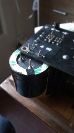
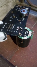
Today I place the Mundorf 4 pin properly on the board, my leds wiring, please see pics bellow, go from capacitor pins OUT+ to OUT-.
Now again music on play, it works like a charm, I strongly believe that expense in C2, is well rewarded, the quality performed is far, far beyond any of my expectations.
Now again music on play, it works like a charm, I strongly believe that expense in C2, is well rewarded, the quality performed is far, far beyond any of my expectations.
Attachments
Hello Magz,
Sorry but your simulation made me do that LC setup. There you used AC as input and the choke before de 10m cap, that's why I made that set-up. A capacitor after the rectification would theoreticaly help, but will be enought?
Thank you !
The AC in the simulation is there to show how the addition of the choke is able to remove any AC ripple riding on the DC, not to show it can be used with pure AC. If the DC has zero ripple (zero AC) the simulation can't show an effect.
Thanks advice Salas, I am into 'Reply to Thread' and loocking below, 'Additional Options', then 'Attach Files', then 'Manage Attachments' so I think I got.
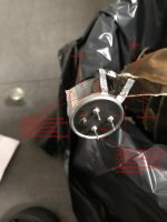
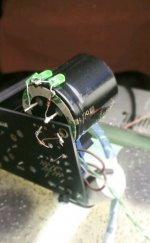
I placed a new pic now, it's my power transformer set up still on the developing board. It may have some interest here:
**** O-Core type transformer, with three secondaries for three Ref-Ds. Is step further over R-Core transformer. I found them very easy to find correct fase polarity by ear. I must mention, is a must also to check correct phase ALSO for SECONDARIES on power transformer, these are independent from PRIMARIES. So please set in phase BOTH, no matter the order. I bought mine on Taobao. Other than that it is aslo Ebay seller: http://www.ebay.com/itm/4N-OFC-O-co...356897?hash=item1ea3b1cae1:g:~vkAAOSwu4BV6T-N
And a higher grade 'Simon Tuned' brand, from their distribuitor in USA:
https://kitsunehifi.com/product/flying-ninja-poster/
**** Instead of a fuse, I use a copper circuit breaker 'ETA' brand, which is also an ON-OFF switch.
**** Sockets and plugs are copper, rhodium plated.
**** Power cable is hand made, Graphene wire isolated with cotton. I glad to share here my extensive research , best quality graphene by my test, come from this manufacturer ???|2D Materials|??????????, There are different thickness from 0,3 to 10mm., I tried all of them, and preferred by a wide margin is 0,6 mm. (around 20USD /metre).
Hi,
What wire does the o-core transformer use? Silver or copper? Thanks.
WYAN
Hi,
What wire does the o-core transformer use? Silver or copper? Thanks.
WYAN
I know my O-core is worse than 'Simon tuned', (and cheaper). But no matter the copper windings, the worse are the lead outs wich are low quality multifiliar silver plated, with PVC dielectric. I plan to remove this so much disgusting PVC, when finally everything is fitted on chassis.
I received a suitable link from my O-CORE manufacturer website, just checked now and I liked.
So here you are:
jamestransformer.com/en_index.html
(not the same JAMES tube output from Taiwan)
Is small business, kind attention, custom transformers took 1 week.
I for a while now, but I remember he recomends me to power three Ref-D, a 80w. core, that one on pic.
I have another smaller, 50 w. core suitable to power one Ref-D only.
It's worth to mention also, on another order, I get a wonderful isolation mains O-Core 600watts, around 5,5Kg., 230v/230v. Very nice just plugged, and astounding after two windings, primary and secondary, were set in phase.
Hello,
I am thinking about using some of my Ref-D in symetric mode,
I mean I want to have /-+5Volts.
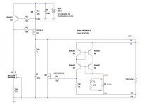
As usual, I don't want to make a mistake, so can anyone please tell me or publish a connection diagram with the explanation?
Thank you!
I am thinking about using some of my Ref-D in symetric mode,
I mean I want to have /-+5Volts.
As usual, I don't want to make a mistake, so can anyone please tell me or publish a connection diagram with the explanation?
Thank you!
Hello,
I am thinking about using some of my Ref-D in symetric mode,
I mean I want to have /-+5Volts.
As usual, I don't want to make a mistake, so can anyone please tell me or publish a connection diagram with the explanation?
Thank you!
You have it at the very bottom of reflector d manual (pdf) 🙂
I know my O-core is worse than 'Simon tuned', (and cheaper). But no matter the copper windings, the worse are the lead outs wich are low quality multifiliar silver plated, with PVC dielectric. I plan to remove this so much disgusting PVC, when finally everything is fitted on chassis.
Thanks. 🙂
Tiofrancotirador, there is a remaining combination IN to OUT, but I don't care, crossing leds this way from the begining to the end of capacitor foil, seems great loss to me much more than IN to IN against OUT to OUT. So, I have no further interests if also such an small benefit, reversing an IN to OUT wiring.
I hope al least the explanation, is understandable, no need to say, I have limited English!
Yesterday for test play, was a great album:
Louis Armstrong & Duke Ellington - Recording togheter for the first time. There is a track 'Cottontail' with an uptempo very useful for quick test on the fly, as I like to do.
That's jazz acoustic small ensemble, very upfront recorded soloists with punch an live captured dinamic sound. To hear changes is more useful focus the attention on players on backstage, but not the powerful battery, I prefer listen changes in the least layer, the weak cello sound.
In first, I need to replace R1 (was almost burnt).
Trough a Resistor 2R5 Caddock and, in series, a wirewound pot 1ohm.
I begin from safety 3R5 to below, hearing the cello on this track.
Leds were placed IN to IN, when I found (turning down the 1R wirewound pot.) the best value for R1, the bass, become a true wooden cello instrument, with same focus, air and everything found on any of the others upfront instruments.
It is time to try leds OUT to OUT.
I think remember, I did'nt notice anything in first, It was only when turned back to IN to IN, when I notice an evident downgrade. Not saying that anything is sounding bad, just ... boring! I wants return again OUT to OUT! It was enough! how to tell... less dark... more... tactile!
I was not hesitant, but repeat one time more, just for you to confirm.
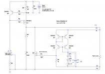
So you're saying:
Out+/- >> In +/- (image 1) >> In+/Out- (image2) ?
Attachments
- Home
- Amplifiers
- Power Supplies
- Reflektor-D builds