Most electronics retailers stock red and green LEDs.
My very old red ones were nice low voltage and low light. 1.6Vf
all my newer (brighter) reds are around 1.8 to 1.9Vf. Green tends to be 1.9 to 2Vf.
So I bought some IR LEDs for the ocassions I need low Vf.
My very old red ones were nice low voltage and low light. 1.6Vf
all my newer (brighter) reds are around 1.8 to 1.9Vf. Green tends to be 1.9 to 2Vf.
So I bought some IR LEDs for the ocassions I need low Vf.
Most electronics retailers stock red and green LEDs.
My very old red ones were nice low voltage and low light. 1.6Vf
all my newer (brighter) reds are around 1.8 to 1.9Vf. Green tends to be 1.9 to 2Vf.
So I bought some IR LEDs for the ocassions I need low Vf.
Thanks. All I can find are close to 2~2.2V and lower-voltage ones seem not easy to locate. 🙂
2 to 2.2V seems very high for Vf.
But that might be explained by the specification using Vf at the maximum permissible current.
When used at a sensible long term current the voltage would be lower.
You would have to look at the datasheet to see how they have specified the device.
Or just buy a dozen and measure them at a range of currents. If Vf is too high find a different model/supplier and try again.
2 to 2.2V seems very high for Vf.
But that might be explained by the specification using Vf at the maximum permissible current.
When used at a sensible long term current the voltage would be lower.
You would have to look at the datasheet to see how they have specified the device.
Or just buy a dozen and measure them at a range of currents. If Vf is too high find a different model/supplier and try again.
Thanks. Will try some from Mouser. 🙂
D
Deleted member 548388
Hi folks,
could someone of you please post a few pics of a finished build? I'm in need of some visual advice for my Reflektor-D full kit that I received from TeaBag the other day.
Many thanks in advance!
Best,
Dominik
could someone of you please post a few pics of a finished build? I'm in need of some visual advice for my Reflektor-D full kit that I received from TeaBag the other day.
Many thanks in advance!
Best,
Dominik
Hi folks,
could someone of you please post a few pics of a finished build? I'm in need of some visual advice for my Reflektor-D full kit that I received from TeaBag the other day.
Many thanks in advance!
Best,
Dominik
img67346 partagé sur ZimageZ
http://i218.photobucket.com/albums/cc53/salas_043/prt-rd_zpsea4400eb.jpg
http://origin.dastatic.com/forums/gallery/data/1956/medium/image-2.jpeg
Firschi,
if you find any usefull pics from those links, could you attach them here so we can all see them and what you did with them.
if you find any usefull pics from those links, could you attach them here so we can all see them and what you did with them.
D
Deleted member 548388
Of course I did some googleing in the first place just like you, clsidxxl.
Since the title of this thread states that people would post their respective builds here, I expected to find at least some pictures of finished reflektor-d boards and/or implementations. IMHO building is way easier if one does have a visualized result. Nevermind.
Since the title of this thread states that people would post their respective builds here, I expected to find at least some pictures of finished reflektor-d boards and/or implementations. IMHO building is way easier if one does have a visualized result. Nevermind.
Of course I did some googleing in the first place just like you, clsidxxl.
Since the title of this thread states that people would post their respective builds here, I expected to find at least some pictures of finished reflektor-d boards and/or implementations. IMHO building is way easier if one does have a visualized result. Nevermind.
Please specify what exactly you want to see on those pictures and what exactly you want to use them for. If you do not do that then every picture will be useless for you.
E.g.: For me was enough what I could google out about reflector. I can not imagine what else could be needed.
In other words: specify your needs so that there is a chance that someone will make and post the photo of reflector that will match your requirements.
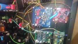
hi ... i have used a ref-d to power my waveio board. Problem is, with remote sensing i only get 4vdc. I checked the ref-d with a 20R dummy load and it outputs 5vdc nicely. Wire length is about 25cm ( quite long, but i couldn't find a shorter way to do it ;-) ) For sense wire i used a shielded cable as suggested. Force wires are awg 18.
Any ideas where i could have gone wrong? Is the wire simply too long? Would love to hear you oppinions. Attached is a picture of my build. Will try to make a nicer one soon

Any ideas where i could have gone wrong? Is the wire simply too long? Would love to hear you oppinions. Attached is a picture of my build. Will try to make a nicer one soon
Attachments
hi ... i have used a ref-d to power my waveio board. Problem is, with remote sensing i only get 4vdc. I checked the ref-d with a 20R dummy load and it outputs 5vdc nicely. Wire length is about 25cm ( quite long, but i couldn't find a shorter way to do it ;-) ) For sense wire i used a shielded cable as suggested. Force wires are awg 18.
Any ideas where i could have gone wrong? Is the wire simply too long? Would love to hear you oppinions. Attached is a picture of my build. Will try to make a nicer one soon
If your voltage is dropping then possibly your device is drawing more current that you predicted. Try 1R resistor (600mA) and see if this works.
Thanks for the reply Tio. I am using 1R resistor already, and have powered the waveio board with the ref-d before successfully. Maybe it draws more current in I2S mode 😕 .Will try bridged mode tomorrow and see if that makes any difference.
Thanks for the reply Tio. I am using 1R resistor already, and have powered the waveio board with the ref-d before successfully. Maybe it draws more current in I2S mode 😕 .Will try bridged mode tomorrow and see if that makes any difference.
Try to short f and s to ground right on the ref d board then. I used to have similar problem with long kelvins in salas bib -/+. With kelvin I got higher voltage indifference than I got from shortening f and s to grounds right on the board.
LTSpice shows that adding a small choke (1.5mH, 518mohm DCR) before the 10mF cap does improve the filtering a lot, especially at higher frequencies. Sim #1 is without choke (L=0), sim #2 is with choke. Output looks stable with no peaking as long as the choke value is kept below ~1.8mH. The choke ought to help with limiting the inrush current as well.
Hello,
I put a 1,5mH choke before the 10000uF cap and I have a doubt about that.
Is use this coke -815-AIRD-02-152K.
I haven't done measurement with a scope yet, but I connect a bypass switch to see(hear) if it is there any improvement on my DAC sound. I couldn't hear any difference by playng music, but if I don't play music and switch the amplifier volume to maximum I could hear a noise in the speakers that disappear if I bypass the choke, so the coke creates a noise, witch is opposite to what it should do. What I am missing?
Try to short f and s to ground right on the ref d board then. I used to have similar problem with long kelvins in salas bib -/+. With kelvin I got higher voltage indifference than I got from shortening f and s to grounds right on the board.
yep, did that and the bridged mode works. I assumed ~20cm length and a shielded wire should work but apparently not ;-) anyway, got my targeted voltage but the waveio still isn't working *lol* well, i guess some more stuff to figure out is also a way to spend my time ;-)
There are two ways to miss some voltage. One is to eventually load it heavier than your load thought would be and it needs higher CCS setting, or oscillation does that. It depends on the load characteristics, sometimes it won't take remote well. Solutions are to try it with more CCS and/or without remote in two wire mode. As you did.
There are two ways to miss some voltage. One is to eventually load it heavier than your load thought would be and it needs higher CCS setting, or oscillation does that. It depends on the load characteristics, sometimes it won't take remote well. Solutions are to try it with more CCS and/or without remote in two wire mode. As you did.
Yeah, it works flawlessly in 2 wire mode. I'm sorry to say I have no way to check for oscillation, but that's probably the problem. Will have to get an oscilloscope sooner or later 🙂
Last edited:
Hello Salas,
In the guide you said to mont the MOSFETS without anny insulator.
The drain touching directly the heat sinks wouldn't be a problem?
In the guide you said to mont the MOSFETS without anny insulator.
The drain touching directly the heat sinks wouldn't be a problem?
For board level sinks that touch each other and not a grounded chassis its OK. The drains are already on the same PSU line you may notice when reading the circuit. The Mini version that sinks to chassis only must be using Silpads, no other option.
For board level sinks that touch each other and not a grounded chassis its OK. The drains are on the same PSU line you may notice when reading the circuit. The Mini version that sinks to chassis only must be using Silpads, no other option.
Interesting idea, I am currently using silpads, but I am guessing that if I only use thermal paste betwen MOSFET and sinks I will get a better thermal dissipation.
Connecting the drain to the sink wouldn't be it acting like an antenna and pick up noise? Or is it insignificant?
Last edited:
- Home
- Amplifiers
- Power Supplies
- Reflektor-D builds