Yes, I tried a faster sweep rate but then the trigger function didn't work correctly.
I think that's too much asked from this cheap scope.
It was good for what you needed and did the job.
") Nice relsult and thanks for posting in the results thread as well.
Nice relsult and thanks for posting in the results thread as well. JT
Hello Snubberfans,
maybe my Quasimodo based Testjig is inspiring to some people here...
Using the original Quasimodo I felt like I needed something more comfortable :
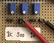
- The Pot went onto a separate board which has jumpers to allow 1k, 500 and 100 Ohm Pots to be jumper-selected.
- Removing the jumper enables Rs measurement without unplugging the Pot
- The Trigger-connection is extended by ~5cm wire, so the Scope-Testhead can be connected more easily
- Having mouted Quasimodo and the Pot extension on a 100x160mm board makes the whole set-up somewhat more stable
See the pictures below.
Greetings,
Winfried
maybe my Quasimodo based Testjig is inspiring to some people here...
Using the original Quasimodo I felt like I needed something more comfortable
:- The Pot went onto a separate board which has jumpers to allow 1k, 500 and 100 Ohm Pots to be jumper-selected.
- Removing the jumper enables Rs measurement without unplugging the Pot
- The Trigger-connection is extended by ~5cm wire, so the Scope-Testhead can be connected more easily
- Having mouted Quasimodo and the Pot extension on a 100x160mm board makes the whole set-up somewhat more stable
See the pictures below.
Greetings,
Winfried
Attachments
Thanks for the feedback!
A friend of mine (not a member here) has tried snubbering with one of his transformers, but gets heavy humming vibration from the trafo when the snubber circuit is connected. Any idea what the cause may be? I haven't seen his set up, though...
Thanks,
Winfried
A friend of mine (not a member here) has tried snubbering with one of his transformers, but gets heavy humming vibration from the trafo when the snubber circuit is connected. Any idea what the cause may be? I haven't seen his set up, though...
Thanks,
Winfried
Thanks for the feedback!
A friend of mine (not a member here) has tried snubbering with one of his transformers, but gets heavy humming vibration from the trafo when the snubber circuit is connected. Any idea what the cause may be? I haven't seen his set up, though...
Thanks,
Winfried
Me thinks there is something bad wrong with his setup.
Thanks for the cudos dear friends!
I did some measurements with an R-Core Transformer in the mean time.
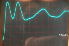
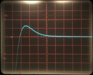
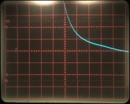
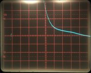
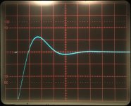
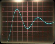
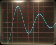
The pictures show traces with open Rs, small overshooting (56Ohms) and without overshoot (17Ohms). well, I'm struggling with the optimization between the last two, because I do not get to the "quasi textbook" traces like some people have shown in the thread.
What may be wrong? Please provide some advice if possible.
Thanks and Regards,
Winfried
I did some measurements with an R-Core Transformer in the mean time.
The pictures show traces with open Rs, small overshooting (56Ohms) and without overshoot (17Ohms). well, I'm struggling with the optimization between the last two, because I do not get to the "quasi textbook" traces like some people have shown in the thread.
What may be wrong? Please provide some advice if possible.
Thanks and Regards,
Winfried
Attachments
@wgh
Man I thought you had it hooked up wrong, but I blew up the photo and it looks like you have it right, but something looks off there. I will wait for one of the others that know more. I wouldn't think either of those values are right... something else appears to be amiss.
Man I thought you had it hooked up wrong, but I blew up the photo and it looks like you have it right, but something looks off there. I will wait for one of the others that know more. I wouldn't think either of those values are right... something else appears to be amiss.
When in doubt, leave everything exactly the same, but replace the transformer by a fixed inductor manufactured by a top tier electronic component company. Something between 40 microhenries and 400 microhenries, for example, any of these:
short-link to possible inductors at Mouser.com
If the scope display is still "ugly" then you know it's not the fault of the R-core transformer, it's the fault of your Quasimodo jig arrangement.
On the other hand if the scope display becomes clean and perfect, like Figure 3 of the Quasimodo .pdf document, with beautiful sinusoidal oscillation, then you know it's not the fault of your Quasimodo jig arrangement. It's your transformer.
I am afraid there is some chance that all the extra wires and connectors and flexibility you added to the bare Quasimodo board, may have accidentally damaged the signal integrity of the test fixture. If you get lousy results with a known-excellent inductor, that's proof your fixture needs improvement.
Thanks for the hints!
Guess I'll build-back to the original set up and see what kind of results I get.
The other finding seems to be, though, that a 1k-Pot is too large in most cases and a 500 or 200Ohms Pot supports easier optimisation (for cases where Rs-opt e.g. is below 50Ohms or so). Another idea to improve optimisation accuracy may be to cascade the 1k with a 200Ohms Pot to get to easier/accurate fine tuning - I may give that a try as well.
Regards,
Winfried
When is doubt, go back to what you know works. I don't know how many times when people change something and go looking all over creation then come back to what they just did. That's the first thing I ask people in other areas cars etc... what was the last thing you did before you had the problem. They always swear that couldn't be the issue... 90% of the time it is.
So your approach is solid, after you do that, if the problem persists, then go back and follow the rest of what Mark said. I have a small known good trans here. I know the values and how it should look. If you need it as a loan to try let me know.
EDIT: Never-mind, you are in Germany lol. I guess the flag should have given me a clue. Doh.
Last edited:
OK - let's take advantage the teaching moment...
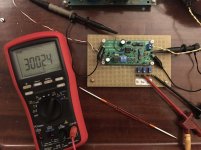
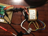
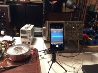
Well, honestly... I have NOT built back, but too a known good 750VA transformer, did a thorough snubber RTFM and then went to measurements. You see my set up in the first image.
Three initial findings:
1. varying Cx can/may be helful, even advisable if Rx values get too low
2. optimising Rx by a "normal" scope trace is a bit tricky (i.e. coarse)
3. my Rx "extension" is not the problem
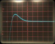
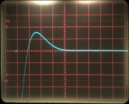
The 750VA measurement (despite the long story, this literally took a few minutes!):
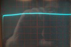
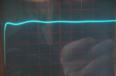
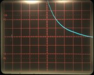
For this I connected the 500Ohm and the 100Ohm Pots in parallel (i.e. two Jumpers) and tuned the 500Ohm first. When I thought "this looks optimal" I increased vertical resolution from 1V/Div. to 50mV/Div. and Ha! ...there's still a hump in the curve! So I went on by slowly tuning down the 100Ohm Pot. to find the optimum. Look at the sequence of measurement traces: The last trace looks OK to me, may be there's a hint of a bump, but so be it
So these are my results for time being, up for discussion and advisory.
Best Regards,
Winfried
Well, honestly... I have NOT built back, but too a known good 750VA transformer, did a thorough snubber RTFM
and then went to measurements. You see my set up in the first image.Three initial findings:
1. varying Cx can/may be helful, even advisable if Rx values get too low
2. optimising Rx by a "normal" scope trace is a bit tricky (i.e. coarse)
3. my Rx "extension" is not the problem
The 750VA measurement (despite the long story, this literally took a few minutes!):
For this I connected the 500Ohm and the 100Ohm Pots in parallel (i.e. two Jumpers) and tuned the 500Ohm first. When I thought "this looks optimal" I increased vertical resolution from 1V/Div. to 50mV/Div. and Ha! ...there's still a hump in the curve! So I went on by slowly tuning down the 100Ohm Pot. to find the optimum. Look at the sequence of measurement traces: The last trace looks OK to me, may be there's a hint of a bump, but so be it
So these are my results for time being, up for discussion and advisory.
Best Regards,
Winfried
Attachments
-
 8 gn-gn opt 1V 80nF 11Ohm 800.jpg169 KB · Views: 107
 -
 7 gn-gn 50mV 80nF Pot var 800.jpg161.6 KB · Views: 103
 -
 6 gn-gn 1V 80nF Pot var 800.jpg162.6 KB · Views: 107
 -
 5 gn-gn 50mV 80nF Pot var 800.jpg169.7 KB · Views: 107
 -
 4 gn-gn 1V 80nF Pot var 800.jpg186.9 KB · Views: 352
 -
 3 gn-gn 1V 80nF Pot var 800.jpg166.7 KB · Views: 356
 -
 2 gn-gn 1V 80nF Pot 100Ohm 800.jpg160.2 KB · Views: 370
 -
 1 gn-gn 1V Pot open 800.jpg174 KB · Views: 392
 -
 Mess- & Fotoaufbau 800.jpg187.6 KB · Views: 382
 -
 9 gn-gn opt 50mV 80nF 11Ohm 800.jpg162 KB · Views: 115
Hi again!
Well, I did not stop the exploration (after the Toroid measured perfectly and showed textbook step response compensation, see previous post), but took the R-core again and also tried another R-core I have:
"Two pieces" is a very small R-core sample, so I'm careful with my opinion, but at least the ringing resonse seems to be different and the snubber optimization is so far not achievable for the R-cores I have (from different sources with different windings) when comparing R-core scope traces (showing minimal ringing) with the documented ones. Sorry, I did not document that this time, may do so if needed when I have my final, less shaky, camera stand...
What is the experience of other R-core snubber users?
Regards,
Winfried
Well, I did not stop the exploration (after the Toroid measured perfectly and showed textbook step response compensation, see previous post
), but took the R-core again and also tried another R-core I have:"Two pieces" is a very small R-core sample, so I'm careful with my opinion, but at least the ringing resonse seems to be different and the snubber optimization is so far not achievable for the R-cores I have (from different sources with different windings) when comparing R-core scope traces (showing minimal ringing) with the documented ones. Sorry, I did not document that this time, may do so if needed when I have my final, less shaky, camera stand...
What is the experience of other R-core snubber users?
Regards,
Winfried
Hi Mark and thanks for the Quasimodo test-jig. I've used it on a couple of new builds and now I look at my older projects with capacitors across the rectifier diodes and realize that I have to revisit them. I've built a bunch of stuff using big common mode chokes between the rectifier bridges and the first capacitors and was wondering if the chokes would affect the resonance point that we are trying to reduce and upset that.
I don't think the stuff downstream of the rectifiers has much effect on the RLC resonant circuit. It's just the leakage inductance of the transformer secondary, the capacitance of the secondary and the rectifiers, and the excess capacitance & resistance if a C+RC snubber is installed.
Has anyone used this to test a transformer that was to be used in a tube amplifier rated in the 50 watt range with the secondary be around 625V or 690V CT @ 150ma, 50V bias?
Using this transformer as the above example:
http://www.classictone.net/40-18054.pdf
Using this transformer as the above example:
http://www.classictone.net/40-18054.pdf
Hello James,
having looked at the complex secondary windings set the first question in my mind was: Which of the connections does the application use ?
And which of the connections used lead to rectification(s) in the actual application?
So far as I understand the snubbing concept, this will determine where snubbers needs to be connected.
Regards,
Winfried
- Home
- Amplifiers
- Power Supplies
- Simple, no-math transformer snubber using Quasimodo test-jig