I have. The Sheffield Drum Record (okay, its compact disc) had a greater sense of immediacy and "air is moving" with snubber than without, played thru an IC linestage whose power supply used an EI core transformer, and ultra high current, ultra narrow charging peaks (less than 0.1% conduction angle). YMMV.Has anyone detected an audible difference after properly snubbing?
I also snubbed a power amp's toroid (link) during assembly; I didn't bother with before/after testing.
Yes; when optimizing a transformer snubber, the test apparatus should include the transformer itself.My short cut is simply connecting the function generator --> C + Cs +R --> oscilloscope.
And see how does the damping change with different values of R. But, it seems that I have not taken the capacitance/inductance of the transformer into account.
Kudos for taking the measurements again and showing the results. They still look and feel wrong to me, severely wrong; so perhaps this will be a learning experience that gives me a Eureka Moment. Meanwhile would you please post the exact model number of the Triad 160VA transformer; I think I may want to purchase one that exactly matches yours, and duplicate your QM results that look and feel so severely wrong.
Please don't be insulted when I ask: did you verify the transformer's phase dots (Quasimodo design note Appendix D)? If you accidentally connected the primaries OR the secondaries with the phase dots wrong, the measured results will be unreliable. For a transformer with primaries in series (230VAC) and secondaries in parallel, the proper connection is shown below.
I will never be insulted. I'm very much a novice learning a lot here and I appreciate the support/tutorials.
The transformer is a Triad Magnetics VPT30-5330. I do not have a signal generator to verify the manufacturer's data sheet but the transformer was operational as wired - I removed it from an operational power supply for connection to Quasimodo. So, as per the data sheet, on the primary side grey is jumpered to violet (series operation for 230V) and on connection to the Quasimodo I "shorted" blue and brown by binding them together. On the secondary side, red and yellow are soldered together and so are black and orange (parallel for 15V). Each pair is connected to the Quasimodo P7. (I believe this conforms to your Fig 13.)
That was a very good idea. Here are the results. Measuring the primaries (in series) with the secondaries shorted. First infinity and second 109R.
I eagerly await interpretation")
(Note I have all the Quasimodo dip switches set to off.)
PS: how do you get thumbnails?
An externally hosted image should be here but it was not working when we last tested it.
An externally hosted image should be here but it was not working when we last tested it.
I eagerly await interpretation
(Note I have all the Quasimodo dip switches set to off.)
PS: how do you get thumbnails?
Well I guess it might be possible that a very high current, very low secondary voltage transformer, might have a secondary with very few turns of very large diameter wire. Such a transformer might have very low secondary leakage inductance. ("LT" in appendix A of the Quasimodo design note). Since the snubber resistance is proportional to sqrt(LT), lower secondary leakage inductance means lower Rsnub @ critical damping {zeta = 1.00}. I suppose it might be possible.
LT would be lower still, for a valve heater transformer that puts out 6.3VAC at huge current. The optimum Rsnub would be astonishingly (to me) low for such a transformer.
If it were me, I think I'd be inclined to try a few more lab experiments, just to accumulate some more confidence in (a) this particular Quasimodo board; (b) this particular Cx capacitor; (c) this particular scope.
I think I'd measure Cx on a capacitance meter. Since I happen to own 3 different capacitance meters, I'd measure it on all 3. Is this Cx really 0.01 microfarads? If I had no capacitance meter, I'd run Quasimodo with several different "0.01uF" capacitors, ideally from different manufacturers. When driving the transformer secondary with different "0.01uF" caps, do the results agree with each other?
I think I'd connect up Quasimodo, Cx, and the scope, to a few different known-value inductors. Then I'd measure the resonant frequency using the scope's "Measure" and/or "Cursor" buttons, kinda similar to the fixed 4700uH inductor testing shown on page 10 of the Quasimodo design note. Resonant frequency "f" depends on Cx and Linductor as shown in equation C.2
Does the measured resonant frequency, equal the theoretical resonant frequency predicted from the inductor value and the capacitor value? I.e. Does Science Work?
I think I'd connect up the transformer secondary to Quasimodo, and try a few different Cx capacitors with different capacitance values. To get nice ringing I'd set Rs = infinity (removed). Each different Cx will resonate with the transformer secondary at a different frequency; I'd extract the transformer's inductance from f_resonant and Cx. If the inductance values all agreed with each other fairly well, that's another good sign that Science Works.
And then after all of that, if Cx was the correct value, and if Cx + Quasimodo resonated a few known-value inductors at the theoretically correct frequencies, and if the transformer secondary inductance measurement was generally repeatable across several different Cx values, I'd have no choice but to accept the data measured in posts #230 and #235. Even with the astonishingly low optimum Rsnub value.
Finally, I should remind everyone that the Quasimodo design note only suggests wattage ratings for snubber resistors between 50 and 500 ohms (page 7). Outside that range you'll need to perform your own calculations or simulations to choose a wattage.
LT would be lower still, for a valve heater transformer that puts out 6.3VAC at huge current. The optimum Rsnub would be astonishingly (to me) low for such a transformer.
If it were me, I think I'd be inclined to try a few more lab experiments, just to accumulate some more confidence in (a) this particular Quasimodo board; (b) this particular Cx capacitor; (c) this particular scope.
I think I'd measure Cx on a capacitance meter. Since I happen to own 3 different capacitance meters, I'd measure it on all 3. Is this Cx really 0.01 microfarads? If I had no capacitance meter, I'd run Quasimodo with several different "0.01uF" capacitors, ideally from different manufacturers. When driving the transformer secondary with different "0.01uF" caps, do the results agree with each other?
I think I'd connect up Quasimodo, Cx, and the scope, to a few different known-value inductors. Then I'd measure the resonant frequency using the scope's "Measure" and/or "Cursor" buttons, kinda similar to the fixed 4700uH inductor testing shown on page 10 of the Quasimodo design note. Resonant frequency "f" depends on Cx and Linductor as shown in equation C.2
(1 / (2 * PI * f)) = sqrt(Linductor * Cx)
Does the measured resonant frequency, equal the theoretical resonant frequency predicted from the inductor value and the capacitor value? I.e. Does Science Work?
I think I'd connect up the transformer secondary to Quasimodo, and try a few different Cx capacitors with different capacitance values. To get nice ringing I'd set Rs = infinity (removed). Each different Cx will resonate with the transformer secondary at a different frequency; I'd extract the transformer's inductance from f_resonant and Cx. If the inductance values all agreed with each other fairly well, that's another good sign that Science Works.
And then after all of that, if Cx was the correct value, and if Cx + Quasimodo resonated a few known-value inductors at the theoretically correct frequencies, and if the transformer secondary inductance measurement was generally repeatable across several different Cx values, I'd have no choice but to accept the data measured in posts #230 and #235. Even with the astonishingly low optimum Rsnub value.
Finally, I should remind everyone that the Quasimodo design note only suggests wattage ratings for snubber resistors between 50 and 500 ohms (page 7). Outside that range you'll need to perform your own calculations or simulations to choose a wattage.
Can I check one thing? Post 54 has a photo with a 1n cap in C2. This is incorrect - right? The build guide has the cap labelled 102J100 in C1 consistent with the BOM.
Going through the above is going to take some time… I doubt the oscilloscope is an issue as it is brand new and was tested by the distributor prior to delivery. I also tested the transformer with different caps (new EPCOS 63V 5% film, B32529C103J and B32529C154J respectively) and got more or less the same result. I may try another transformer next.
Going through the above is going to take some time… I doubt the oscilloscope is an issue as it is brand new and was tested by the distributor prior to delivery. I also tested the transformer with different caps (new EPCOS 63V 5% film, B32529C103J and B32529C154J respectively) and got more or less the same result. I may try another transformer next.
Last edited:
Yes the photo attached to post 54 shows a 1 nF capacitor plugged into the Cx = C2 socket. That's not the recommended starting value for Cx = C2. The recommended starting value for Cx = C2 is 10nF (0.01uF), which is the number printed on the front side silk screen of the PCB (middle image of post 54), and discussed at length in the Quasimodo design note.
I must have been fooling around with Quasimodo-and-math (Appendix C) experiments, where resonant frequency is measured for different values of Cx = C2, and I guess I snapped that photo when a 1 nF capacitor happened to be in the socket. Sorry if it caused confusion.
I'm pretty sure the QM V4 kit-of-all-parts only included a single 1nF capacitor, which is soldered into the "C1" position and thus, not available to be plugged into the Cx = C2 socket. I'm pretty sure that after soldering all components into their positions, the only two "left over" components would have been an 0.01uF capacitor {to be plugged into the Cx = C2 socket} and an 0.15uF capacitor {to be plugged into the Cs = C3 socket}.
Today's inexpensive digital multimeters usually contain a capacitance measurment function; they can serve as a peace-of-mind doublecheck when selecting and installing capacitors. (example from Amazon UK)
Thanks. No problem. I had followed the build guide but had previously printed out that photo and marked it up for how/where to connect each scope channel. As I was running the Quasimodo with the other set of caps I glanced down and saw the caps (1n in Cx and a blue cap in C1) and had a mild dose of anxiety.
New transformer. RKD 160/2X15 - BLOCK - TRANSFORMER, 2 X 15V, 160VA | Farnell UK Same wiring scheme (230V series primary, 15V parallel secondary)
28R is the answer from Quasimodo
I will post pics at some point tomorrow or Saturday.
28R is the answer from Quasimodo
I will post pics at some point tomorrow or Saturday.
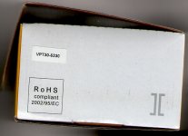
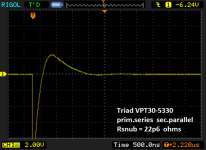
It took some strenuous negotiation, and a plate of cookies, but I was able to borrow a copy of SGK's transformer that he used in posts #230 and #235. A scan of the product packaging is below, showing the model number: VPT30-5330.
I verified that this transformer's phase dots were marked correctly, using the procedure in the design note appendix D.
Copying SGK's setup (series primaries (230V), parallel secondaries (15VAC)), I connected it to a known-good Quasimodo and a known-good oscilloscope. Capacitors Cx=0.01uF and Cs=0.15uF were measured with a capacitance meter, and inserted into the Quasimodo sockets.
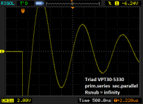
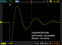
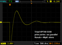
As I slowly dialled the trimpot down, I got the sequence of photos below. In my opinion, this particular transformer was critically damped (zeta = 1.0) with Rsnub = 22.6 ohms. This Rsnub is lower than I measured for my Avel Lindberg toroid with two 35V secondaries in series; but the lower voltage and the parallel secondaries probably explains the difference.
SGK, I recommend that you measure the ringing frequency of your transformer when Rsnub = infinity, and compare that to the ringing frequency of this borrowed transformer on the Rsnub=infinity picture below. If the two ringing frequencies are about the same, the two optimum Rsnub values will be about the same too.
I verified that this transformer's phase dots were marked correctly, using the procedure in the design note appendix D.
Copying SGK's setup (series primaries (230V), parallel secondaries (15VAC)), I connected it to a known-good Quasimodo and a known-good oscilloscope. Capacitors Cx=0.01uF and Cs=0.15uF were measured with a capacitance meter, and inserted into the Quasimodo sockets.
As I slowly dialled the trimpot down, I got the sequence of photos below. In my opinion, this particular transformer was critically damped (zeta = 1.0) with Rsnub = 22.6 ohms. This Rsnub is lower than I measured for my Avel Lindberg toroid with two 35V secondaries in series; but the lower voltage and the parallel secondaries probably explains the difference.
SGK, I recommend that you measure the ringing frequency of your transformer when Rsnub = infinity, and compare that to the ringing frequency of this borrowed transformer on the Rsnub=infinity picture below. If the two ringing frequencies are about the same, the two optimum Rsnub values will be about the same too.
Attachments
Hi Mark,
Here's an idea: What about characterizing a well-known and readily available trafo so that people can verify their Quasimodo builds and scopes?
It needs not be a trafo which will be fit for mains powered applications, just something which will tune to an Rsnub within the range of the trimpot.
Børge
Here's an idea: What about characterizing a well-known and readily available trafo so that people can verify their Quasimodo builds and scopes?
It needs not be a trafo which will be fit for mains powered applications, just something which will tune to an Rsnub within the range of the trimpot.
Børge
Recommended practice with Quasimodo is to use a CRC snubber having Cx much much greater than (Ctransformer + Crectifier). This creates a resonant RLC circuit whose R is known (it's Rsnub), whose C is known (it's Cx), and whose L is unknown (it's the transformer's secondary leakage inductance).Here's an idea: What about characterizing a well-known and readily available trafo so that people can verify their Quasimodo builds and scopes?
Thus Quasimodo is simply a machine which measures inductance.
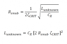
QM reports its measured inductance in a convoluted way, that happens to be especially user friendly: it tells you the value of Rsnub which gives critical damping (zeta = 1.00). This is the number that circuit designers actually want: it's the final component value of an optimum snubber. Naturally Rsnub is mathematically related to the unknown inductance:
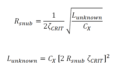
where zeta_crit = 1.00; i.e. I'm defining "optimum snubber" to mean "RLC resonant circuit whose damping factor equals 1.00".
What's a good way to calibrate a machine which measures inductance? Have it measure some inductors whose values are known beforehand. I think fixed inductors are best for this job; their inductance is specified and the tolerance of their inductance (± 5%? ± 10%?) is also specified. Transformer secondary leakage inductance is not specified and neither is its tolerance. In a population of 3, or 30, or 300 "identical" transformers from the same manufacturer, we have no idea how closely their secondary leakage inductances should match. After all, leakage inductance is a second-order phenomenon, a "parasitic" inductance that is neither observed nor directly controlled in the manufacturing process.
So I think the best way to tell whether your Quasimodo board is working, is to hook it up to a 10%-tolerance fixed inductor and measure that inductance.
If somebody wants to choose a transformer, dub it "the platinum QM reference," and publicize their QM measurement results on that transformer, ... , well, I can't stop you. But I don't think it's an especially good idea.
MJ
Attachments
It took some strenuous negotiation, and a plate of cookies....
Mark, thanks a lot for doing this. At least I am not going completely mad. I'll now look at a model for power dissipation.
- Home
- Amplifiers
- Power Supplies
- Simple, no-math transformer snubber using Quasimodo test-jig