Without C13 the circuit is prone to oscillate, but with C13 in place the circuit is stable. I have done several test with different loads without any issue.
Usually circuits that are prone to oscillation have limited phase margin and thus limited damping properties. Thus we were curious.
The PCB is already designed to be used as positive and negative output, there are a pair of jumper to set, some components polarity to reverse and all the bjt to be replaced with their complimentary type.
Sound awesome! I'm looking forward to the final version of the module!
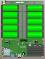
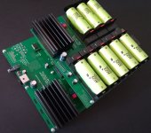
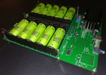
LiFePo4 Battery Power Supply
This is a preview of the new LiFePo4 battery power supply system.
From left to right:
- TWRPS-LBS-M Main board and control
- TWRPS-LBS-D Additional board controlled by the main board
- TWRPS-LBS-P Power supply unit and batteries recharge
This is a preview of the new LiFePo4 battery power supply system.
From left to right:
- TWRPS-LBS-M Main board and control
- TWRPS-LBS-D Additional board controlled by the main board
- TWRPS-LBS-P Power supply unit and batteries recharge
Attachments
The main board has 4 independent and configurable output rails:
- 3V3 to 16V5, typically for oscillators
- 2 x 3V3 to 6V6, typically for DAC
- 3V3, auxiliary devices (for example the clock section of the FIFO)
The main board also controls all the system, normal operation and recharging.
There is an optional 5V/500 mA linear regulator to supply other devices like USB to I2S and so on.
No switching devices or active oscillators during listening, no RF at all (no switching display and microcontroller in stad-by mode).
The daughter board provides 2 more output rails:
- 2 x 3V3 to 13V2, typically for DAC output stage.
It's controlled by the main board.
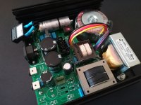
The PSU board provides:
- linear supply to recharge the batteries
- linear supply to power the FIFO board
- regulated supply to power the oscillators while recharging the batteries, to never shut down the oscillators
There will be 3 diy options:
- bare boards (main board with micro installed and programmed)
- semi-finished board, all bottom smd parts mounted, top TH parts to be sourced and soldered
- finished boards (PSU board without transformers to avoid high shipping cost)
- 3V3 to 16V5, typically for oscillators
- 2 x 3V3 to 6V6, typically for DAC
- 3V3, auxiliary devices (for example the clock section of the FIFO)
The main board also controls all the system, normal operation and recharging.
There is an optional 5V/500 mA linear regulator to supply other devices like USB to I2S and so on.
No switching devices or active oscillators during listening, no RF at all (no switching display and microcontroller in stad-by mode).
The daughter board provides 2 more output rails:
- 2 x 3V3 to 13V2, typically for DAC output stage.
It's controlled by the main board.
The PSU board provides:
- linear supply to recharge the batteries
- linear supply to power the FIFO board
- regulated supply to power the oscillators while recharging the batteries, to never shut down the oscillators
There will be 3 diy options:
- bare boards (main board with micro installed and programmed)
- semi-finished board, all bottom smd parts mounted, top TH parts to be sourced and soldered
- finished boards (PSU board without transformers to avoid high shipping cost)
The main board has 4 independent and configurable output rails:
- 3V3 to 16V5, typically for oscillators
- 2 x 3V3 to 6V6, typically for DAC
- 3V3, auxiliary devices (for example the clock section of the FIFO)
The main board also controls all the system, normal operation and recharging.
There is an optional 5V/500 mA linear regulator to supply other devices like USB to I2S and so on.
No switching devices or active oscillators during listening, no RF at all (no switching display and microcontroller in stad-by mode).
The daughter board provides 2 more output rails:
- 2 x 3V3 to 13V2, typically for DAC output stage.
It's controlled by the main board.
The PSU board provides:
- linear supply to recharge the batteries
- linear supply to power the FIFO board
- regulated supply to power the oscillators while recharging the batteries, to never shut down the oscillators
There will be 3 diy options:
- bare boards (main board with micro installed and programmed)
- semi-finished board, all bottom smd parts mounted, top TH parts to be sourced and soldered
- finished boards (PSU board without transformers to avoid high shipping cost)
This looks really interesting! Looking forward to some price estimates on your three options. Great work!
As for the TWRPS-UGL there are 3 options: bare board, semi-finished board and finished board.
One option only for TWRPS-pp: bare PCB.
One option only for TWRPS-pp: bare PCB.
Last edited:
Thanks Andrea ,you did a great job with the power supply too,have you made some measurements on these?
apparently according to the reports the Salas SSV1.3 ultra BIB work very well too.
apparently according to the reports the Salas SSV1.3 ultra BIB work very well too.
Thanks Andrea ,you did a great job with the power supply too,have you made some measurements on these?
apparently according to the reports the Salas SSV1.3 ultra BIB work very well too.
We have measured the oscillators with both regulators and the phase noise plots is superimposable to the one powered with batteries.
BTW, as I already said, if you look for the best we suggest battery power supply for all the digital chain.
Are they all "+ & Gnd" power suplies ?
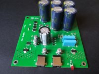
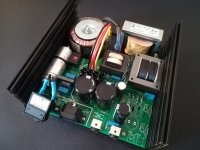
Are the big blue caps Panasonic FC ?
The TWRPS-UGL is a 15V fixed regulator, the TWRPS-pp is a variable regulator that cand be reversed to get negative rail instead of positive.
Yes, the big blue capacitors are Panasonic FC, and the black caps are Nichicon UKL.
Andrea then I ask you if you have compared the two types of power supply,thanks.
TWRPS-UGL vs TWRPS-pp
TWRPS-UGL vs TWRPS-pp
Last edited:
As I said in post #152 both regulators perform the same supplying the oscillators, the only difference is that the TWRPS-pp can supply 2 oscillators + 2 doublers while the TWRPS-UGL is able to supply 2 oscillators or 1 oscillator + 1 doubler.
Thank you Andrea, it is true that you had specified the two regulators, excuse me I had not seen it.
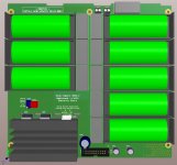
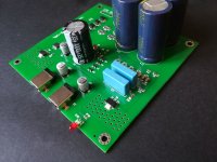
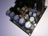
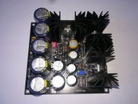
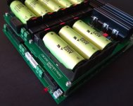
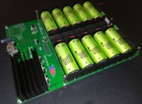
LiFePo4 battery supply system
The LiFePo4 battery supply system TWRPS-LBS is ready and tested, I attach a few pictures of the finished boards (PSU, Main board and optional Extra board to expand the available rails).
We will provide 3 options:
- bare boards (users solder all the parts except for the MCU that is provided assembled and programmed)
- semi-finished boards (users solder a few parts, mostly trough hole)
- finished boards (fully assembled and tested)
Attachments
Hi Andrea.
I hope everything is fine & well with you.
I must say that I greatly admire your dedication to the subject.
It almost seems like you are working 75 hours/day 😀 You are just building everything!
Best regardsd: Alex
--------------------------------------
PS:
A colleague of mine mentioned of a mathematician by the name of Andrea Mori. That cannot be you. Or can it?
Hi Alex,
no, it's not me the mathematician.
Now we are two, me and my co-developer therefore we are more prolific.
We are trying to build the audio system of the life!
But the free time is so little ...
no, it's not me the mathematician.
Now we are two, me and my co-developer therefore we are more prolific.
We are trying to build the audio system of the life!
But the free time is so little ...
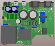
TWRPS-pp Low noise push-pull regulator
AC input
10 to 16 Vdc output
Power supply for: 2 x oscillators + 4 x frequency doublers
Board size: 107mm x 102mm
Board options: bare PCB only
Note: all parts are through hole
AC input
10 to 16 Vdc output
Power supply for: 2 x oscillators + 4 x frequency doublers
Board size: 107mm x 102mm
Board options: bare PCB only
Note: all parts are through hole
Attachments

- Home
- Amplifiers
- Power Supplies
- The Well Regulated Power Supply