I seem to remember Goudreau recommending in his 'triplet' posts that a regulator should be deliberately kept narrowband - used only at the LF end upto a kHz or so where it has plenty of gain (and feedback) in hand - with the mid to HF end handled entirely passively with parallelled caps located right at the pins of the device being powered.
Makes sense really. Why try to squeeze every bit out of a device that clearly isn't meant to work at HF?
Makes sense really. Why try to squeeze every bit out of a device that clearly isn't meant to work at HF?
Gopher said:I seem to remember Goudreau recommending in his 'triplet' posts that a regulator should be deliberately kept narrowband - used only at the LF end upto a kHz or so where it has plenty of gain (and feedback) in hand - with the mid to HF end handled entirely passively with parallelled caps located right at the pins of the device being powered.
Yes, makes sense to me too. I grow increasingly skeptical of the real-world performance of the super-regulators claiming near-zero output impedance up to 200kHz. I'm still waiting for someone to post the Z/phase curve of one of these. Not a model - a real one.
There are definite tradeoffs using remote ground sensing with these regs. The increased definition and "slam" in the low end comes at the price of aggressive-sounding trebles, and there's no way around it. The longer the sense wires, the worse it gets. It's not a worthwhile tradeoff, in my opinion. The upper four octaves are so much smoother and more transparent with the adjust RC components grounded at the supply.
With the Rbuffer in place, the output caps' value and ESR are the determining factor in the Z/phase linearity. And, they determine the tonal character AND spatial tilt of the sound field as well. (By "spatial tilt", I mean the accuracy of the front-to-back and height imaging.)
As noted previously, with the 470uF output caps, the sound was tilted forward and the perceived tonal balance was definitely on the bright side. And the phase curve was tilted up a bit on it. With the 1000uF output caps, it was definitely a recessed, warm, polite presentation (far too much so), and spatially tilted back. And it's phase curve had a downward tilt before the inductive break upward.
So the power supply phase linearity has a definite affect on imaging, as well as perceived tonal balance.
The best phase linearity was with about 600uF of capacitance. The closest I had on hand that would fit on the Sony DAT's power supply board was some 560uF with .040 ohms ESR, so I installed those. The curves below are of the modified supplies in the Sony. There was no place on the top of the supply board to attach the test clips to, so I sliced away some insulation from the supply leads about 3" above the board. That's why the curves are a few milliOhms above the measurements made on the test fixture.
The phase linearity is actually better than it measured on the fixture, which is a pleasant surprise, from 0 to 10º up to 10kHz. One can't complain when the real-world performance exceeds the breadboard! No doubt that will worsen at the top end before it gets to the circuits on the board, but it's an excellent figure. The rail-to-rail matching isn't quite as good as the test fixture, because the idle current draw on the + rail is a good 50mA higher than the - rail and that lowers it's impedance a bit. I may disconnect some things not being used to even them out.
I've been listening all night, and the sound is really superb. No question, this is the best 2-channel holography I've ever heard. It put me back in the mode of "oh, I wonder what this cd sounds like now..." and it sounds great. With well-recorded ensembles and orchestral works, the holography is stunning. No doubt, there's room for improvement. But this is the best I've ever heard.
Attachments
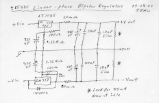
jbau can you post a drawing of this latest configuration please so there's no confusion about terminology and values.
jbau said:
Yes, makes sense to me too. I grow increasingly skeptical of the real-world performance of the super-regulators claiming near-zero output impedance up to 200kHz. I'm still waiting for someone to post the Z/phase curve of one of these. Not a model - a real one.
As a newcomer I've been also chasing that "golden" regulator. Before you posted results on the 317/337 regs I have used them and could clearly hear the sound difference between them and a particular shunt regulator (salas) that I had built on a whim. The difference was not subtle; I'm a person with equipment (ears included) that can hardly hear the difference between two different capacitors in the same circuit. Also before seeing this thread, I went the route of building/designing yet another regulator, shunt too, trying to achieve low output impedance and with a flat profile (phase too) into the kHz range. It is not a super regulator, but I would like to have it measured and see if indeed the only good thing about it is its simulated results, but sadly, I don't have the proper equipment. I would be happy to send you such a regulator if you would agree to run one of your quick tests on it. It is not as easily adjustable as a lm317 though, so I will have to build it to your specifications: desired voltage out, idle load current, expected max load current swing.
Regards.
We can continue privately. I am not by nature very careful about such things. However, one thing we have not addressed privately is the specs for the regulator to send. I thought that would not be duplicate.
Edit: but I think I see a reason to decide on this privately; perhaps it is better to keep the thread focused on results.
Edit: but I think I see a reason to decide on this privately; perhaps it is better to keep the thread focused on results.

here is what the data sheet says about protection diodes on the LT1085:
In normal operation, the LT1083 family does not need any protection diodes. Older adjustable regulators required protection diodes between the adjustment pin and the output and from the output to the input to prevent overstressing the die. The internal current paths on the LT1083 adjustment pin are limited by internal resistors. Therefore, even with capacitors on the adjustment pin, no protection diode is needed to ensure device safety under short circuit conditions.
Diodes between input and output are usually not needed. The internal diode between the input and the output pins of the LT1083 family can handle microsecond surge currents of 50A to 100A. Even with large output capacitances, it is very difficult to get those values of surge currents in normal operations. Only with a high value of output capacitors, such as 1000μF to 5000μF and with the input pin instantaneously shorted to ground, can damage occur. A crowbar circuit at the input of the LT1083 can generate those kinds of currents, and a diode from output to input is then recommended. Normal power supply cycling or even plugging and unplugging in the system will not generate current large enough to do any damage.
A couple notes relating to board layout that explain the measurement differences between the test fixture and the supply as installed in the Sony DAT.
The major difference has to do with layout and the large spacing for leads on every component in the test fixture. The fixture was put together on perforated glass board with solder standoffs to allow ease of component changes and use of both axial and radial lead components. All passive components have about 2.5" spacing between solder points. The regulators are soldered to the standoffs with full lead lengths. As a result, there is more inductance in all leads than there is in a pc board laid out for radial components. And that accounts for the greater rise in Z and phase shift in the fixture vs the Sony supply.
I originally thought that the approx. .005 Ohm mismatch between the regs (with consequent phase mismatch) as installed in the Sony was due to the higher quiescent load current on the LT1085. Well, it turns out not to be. The cause is, the Sony's regulator pc board layout is not symmetrical. The trace from the (-) regulator output to the Rbuffer is about 1.5" longer than the one from the (+) output, and it measures about .005 Ohms higher. Paralleling that trace run with a 20 ga. jumper wire took care of most of it and brought the Z and phase curves much tighter together.
So the most important layout consideration for best Z/phase linearity and matching is: regulator out -> Rbuffer -> output capacitor -> ground path. That's the critical loop. Make sure the path lengths are the same, and the shorter the better. The adjust-to-ground RC's aren't as critical, and can have longer traces. But still, make their paths the same length. And as always in 2-channel audio, symmetry is a good thing.
Someone asked what 560uF 'lytic capacitor I used on the output. It is a Nichicon PW series, 560uF/35V. They were pulled from a defective SMPS I had laying around. Rated ESR is .045 ohms, these two measured .040 and .039 ohms. There are probably better caps available.
You might of already covered this, but from my weak memory, don't some of the newer LT Vregs need low esr caps right at the output for stability (internal wide band error amps?). I think they wanted at least a few uF of tantalums?
I don't see any signs of instability. These regulators are more stable under load than they are with little or no load. And the ESR of a 560uF cap plus 20milliohms is lower than the ESR of the 150uF 'lytic they suggest for worst-case conditions. If you're worried about it, put the 22uF tantalum cap they suggest at the LT1085 output pin to ground, it will have little to no impact on the Zout over the audio range.
The data sheet doesn't specify a low-esr cap, it only mentions the esr difference between aluminum lytics and solid tantalums.
The data sheet doesn't specify a low-esr cap, it only mentions the esr difference between aluminum lytics and solid tantalums.
Ok then, FWIW It might be fun to build a little Mosfet load step circuit to check stability and dynamics. You know with a pulse gen, low side TO-92 mosfet and a couple of resistors.
infinia said:Ok then, FWIW It might be fun to build a little Mosfet load step circuit to check stability and dynamics.
If you need to see things from a time domain point of view, then do it. The plots of Z/phase vs load current are a more detailed way to view the same phenomena, and that's already been posted.
step function ie large signal vs small signal are not really equivalent. you know like in control systems.
Not getting defensive, just keeping things in proper context. The step function load test is irrelevant for a circuit that is only drawing current in the audio range. To make your measurement relevant, limit it's risetime to the freq range of interest; you can make any device look bad by stimulating it above it's operating range. As long as it's stable up there, that's all that matters here.
And... if the output impedance doesn't change with increased load within the range it's being used, a current step test will show no change.
And... if the output impedance doesn't change with increased load within the range it's being used, a current step test will show no change.
It's just an real easy way to check stabilty or getting close to unstable since I saw you are starting to add output impedance. I'm sorry if I didn't follow all your previous experiments.
No problem. It's been a long series of posts... I don't blame anyone for not reading through it all.
- Status
- Not open for further replies.
- Home
- Amplifiers
- Power Supplies
- Another look at the LM317 and LM337 regulators