That will be nice. Remember to use a hefty mains transformer, about 200VA(W). 140mA constant current is going to challenge a smaller transformer in practice, it will drop and heat enough. What kind of circuit application are you going to power, that needs 72mA idle current? 2 channels?
One more question since somebody else already asked about the LED's...
I am just putting together a CRC element to be used before the regulator (as in my schematic).
When calculating the voltage drop across the resistor I do have to use about twice the current draw
of my circuit then... (pretty much same question as sesquilatera)?
I am going to use 6D22s damper diodes as rectifiers and will have a custom mains transformer wound,
so very slowly things are getting along...
Your resistor is going to drop I*R. I=CCS current. That constant current is good to be set at least twice the one you will really use in your audio circuits so to contain dynamic demands. More CCS current is good in general for psu quality and ease, but in a high voltage application as the one we discuss here, it creates significant dissipation and you have to be conservative. In case you consider heroic heat sinking, then the sky is the limit.
salas said:What kind of circuit application are you going to power, that needs 72mA idle current? 2 channels?
My application is a version of Dave Davenport's differential preamp using 6h6 set at 18ma per triode.
http://www.raleighaudio.com/figure_18.htm
salas said:Then set the CCS for 140mA. Your sinking needs will be 18W for Q3 using your intended load circuits and 7W for Q1. I would find a nice 30W sink and bolt both on it.
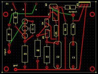
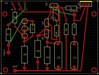
Attached is an updated pcb layout incorporating Salas's suggestions. Being a tubes guy, I do not have much experience with large heat sinks. If I were to use a common 30W sink for both mosfets, do you have any specific component suggestions? Do you see any other layout issues?
Thanks, Salas, for posting the circuit and your help.
Attachments
My attempt in building the HV shunt reg also is making some progress.
I have assembled the CRC module that will go before the regulator,
and I have populated most of the parts of the regulator board (see pic).
I have not soldered the Mosfets yet since I'm still working on the
layout... but I'm getting close. The left heatsink will be cut down
some so I can probably still get to the resistors (not assembled yet)
when they need to be changed (just in case).
Then it's time to double- and triple check all connections (this being
my first HV regulator)... and wait for the transformer that I haven't ordered yet
Edit: @those heatsinks will have to take care of 75mA max so I think they are ample large...
I have assembled the CRC module that will go before the regulator,
and I have populated most of the parts of the regulator board (see pic).
An externally hosted image should be here but it was not working when we last tested it.
I have not soldered the Mosfets yet since I'm still working on the
layout... but I'm getting close. The left heatsink will be cut down
some so I can probably still get to the resistors (not assembled yet)
when they need to be changed (just in case).
Then it's time to double- and triple check all connections (this being
my first HV regulator)... and wait for the transformer that I haven't ordered yet
Edit: @those heatsinks will have to take care of 75mA max so I think they are ample large...
sesquialtera said:
Attached is an updated pcb layout incorporating Salas's suggestions. Being a tubes guy, I do not have much experience with large heat sinks. If I were to use a common 30W sink for both mosfets, do you have any specific component suggestions? Do you see any other layout issues?
Thanks, Salas, for posting the circuit and your help.
For heat sink, 1C/W will do. Something like this one. Check the orientation of Q4 & Q5, I think they need to be turned around for correct positioning. Also Q1 pads spacing looks wide. Is it really so wide?
Stixx said:My attempt in building the HV shunt reg also is making some progress.
Stixx, beautiful progress.
Zen Mod said:salas - did I told ya Fugly! for your shunt reg ?
( now I did ..... )

OK, now it is officially blessed.
Cheers!

salas said:
For heat sink, 1C/W will do. Something like this one. Check the orientation of Q4 & Q5, I think they need to be turned around for correct positioning. Also Q1 pads spacing looks wide. Is it really so wide?
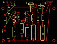
Thanks for the heatsink suggestions and for spotting my errors! I seem to have mis-read the dimensions on the TO-247 datasheet...
Attached is (hopefully) a final version.
Attachments
sesquialtera said:
Thanks for the heatsink suggestions and for spotting my errors! I seem to have mis-read the dimensions on the TO-247 datasheet...
Attached is (hopefully) a final version.
Looks good to me, but double check before you etch.
Hi Salas
been ordering part for this shunt reg. just wondering if there need to do some adjustment for output voltage of 140v and current around 40mA using the 1st schematic? i guess this shunt reg will deliver more than triple than required current. think its good right?
one channel only draw 20mA. do you suggest i run 2 shunt reg or just share a single one?
any help really appreciated
sesquialtera, the pcb you design is base on Salas' shunt reg is for sale or personal use? if you make it.. i would like to have 2 pls
regards, Erwin
- Home
- Amplifiers
- Power Supplies
- Simplistic MosFET HV Shunt Regs