No updates... due to other, more pressing matters, I just stopped and put the panels away and didn't start/finish the electronics.
Never the less, I just pulled the panels out of storage and try to give it go to get them working or send them up into a burst of flame") . I am actually worried about that, despite the fact there is spacer tape everywhere it should be, the wood framing twisted and warped as I was finishing things so I am worried the membrane is a little closer than it should be in places and I will get arcing.
. I am actually worried about that, despite the fact there is spacer tape everywhere it should be, the wood framing twisted and warped as I was finishing things so I am worried the membrane is a little closer than it should be in places and I will get arcing.
If I had it to do again, I would use plywood with LOTS of layers for stability or use plastic. I feel kind of dumb going thru the trouble and expense of using solid walnut when I plan to cover them with silkscreen anyways.
My biggest hangup right now is figuring out a way to mount the resistor bank. I didn't plan the design of that very good. I have some circuit boards from Ken Seibert but they may not work/fit. Fortunately, making up my own custom circuit boards is pretty easy and it's pretty cheap to get them made overseas.... so I may end up doing that.
Now I need to get my head back into this and remember everything I've forgotten (which is alot.
Never the less, I just pulled the panels out of storage and try to give it go to get them working or send them up into a burst of flame
. I am actually worried about that, despite the fact there is spacer tape everywhere it should be, the wood framing twisted and warped as I was finishing things so I am worried the membrane is a little closer than it should be in places and I will get arcing. If I had it to do again, I would use plywood with LOTS of layers for stability or use plastic. I feel kind of dumb going thru the trouble and expense of using solid walnut when I plan to cover them with silkscreen anyways.
My biggest hangup right now is figuring out a way to mount the resistor bank. I didn't plan the design of that very good. I have some circuit boards from Ken Seibert but they may not work/fit. Fortunately, making up my own custom circuit boards is pretty easy and it's pretty cheap to get them made overseas.... so I may end up doing that.
Now I need to get my head back into this and remember everything I've forgotten (which is alot
.No updates... due to other, more pressing matters, I just stopped and put the panels away and didn't start/finish the electronics.
Never the less, I just pulled the panels out of storage and try to give it go to get them working or send them up into a burst of flame
If I had it to do again, I would use plywood with LOTS of layers for stability or use plastic. I feel kind of dumb going thru the trouble and expense of using solid walnut when I plan to cover them with silkscreen anyways.
My biggest hangup right now is figuring out a way to mount the resistor bank. I didn't plan the design of that very good. I have some circuit boards from Ken Seibert but they may not work/fit. Fortunately, making up my own custom circuit boards is pretty easy and it's pretty cheap to get them made overseas.... so I may end up doing that.
Now I need to get my head back into this and remember everything I've forgotten (which is alot
Thanks for the update. Good luck with the completion of your build.
I am worried the membrane is a little closer than it should be in places and I will get arcing.
As long as you used a high resistance coating and large value bias resistor, arcing between diaphragm and stator isn't much of a concern. There's not enough current there to damage much beyond the diaphragm coating. It may limit your ultimate output, but shouldn't be a big problem beyond that.
With good insulation on the stators, there's even less concern.
Thanks... right my objective is to get some kind of sound out them. So I am trying to get my head back into what I need for my resistor banks.
According to bolsert's spreadsheet for my panels I need approx 50k ohms of resistance per segment. I'm not terrible concerned about the precise ohms I need since I will be crossing above the LF dip. A little more resistance is preferable to a little less.
Right now trying to figure out what the minimum number of resistors I need in the segments for power dissipation. I am trying to conserve how "wide" the resistor array is given my panel width constraints.
I think I can get away with 5 in the "1st" and 4 in the second etc... down to 2 in the outer segments with 2W resistors.
I currently have these in my possession. Trying to come up with a way to use them:
(all 2W, high voltage resistors)
100X 8.2K
100X 13K
300X 9.1K
If I have to buy new, then so be it.
So hard to get my head back into this after so long.
According to bolsert's spreadsheet for my panels I need approx 50k ohms of resistance per segment. I'm not terrible concerned about the precise ohms I need since I will be crossing above the LF dip. A little more resistance is preferable to a little less.
Right now trying to figure out what the minimum number of resistors I need in the segments for power dissipation. I am trying to conserve how "wide" the resistor array is given my panel width constraints.
I think I can get away with 5 in the "1st" and 4 in the second etc... down to 2 in the outer segments with 2W resistors.
I currently have these in my possession. Trying to come up with a way to use them:
(all 2W, high voltage resistors)
100X 8.2K
100X 13K
300X 9.1K
If I have to buy new, then so be it.
So hard to get my head back into this after so long
.Attachments
On my latest speakers I also used 2W resistors: (4) then (3), (3), (2), (2), (2) & (2), as shown in the photo below. No doubt I could have gotten by with just one resistor on the final three segments.
I'm bi-amping my speakers with a pair of stereo 225W/channel power amps, playing them at ridiculous volume and it's not a problem.
I'm bi-amping my speakers with a pair of stereo 225W/channel power amps, playing them at ridiculous volume and it's not a problem.
Attachments
Check your PM box
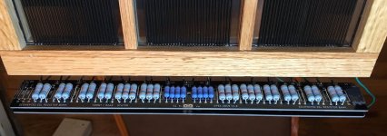
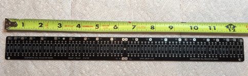
I got those boards from a guy in Canada who built a pair of speakers from my drawings. His boards were setup to feed 11 segments and my new panels had only eight so I cut some off each end to fit.
I got those boards from a guy in Canada who built a pair of speakers from my drawings. His boards were setup to feed 11 segments and my new panels had only eight so I cut some off each end to fit.
Attachments
Last edited:
Will do (nothing there yet).
Trying to figure out what the hell I was thinking given that I need somewhere around 50 kohms and no 2 of the resistors I have will come even close to that.
Seems they are exactly half of what I need. I think I'm reading the spreadsheet/schematics right. ~50kohms in "front" of a segment and ~50 kohms "behind" a segment.
Of course, center segment gets no resistance, ~1ohm on the primary of the stepups.
I wanted to note something interesting. I asked in this thread long ago if it is possible to measure the actual capacitance of the sections/panel versus the theoretical based upon bolsert's spreadsheet. Back then, I didn't have a meter I could use for this....now I do. So just for fun I measured the capacitance.
I'm not sure if I did it right or the readings are even remotely accurate but here's what I got.
I put one meter lead on the charge ring lead and used the other to measure the individual segments (one "side" of the stator).
I consistently measured exactly 40pF across all sections EXCEPT the exact center 5 segments... which are in the "widest" section between the vertical spacers. For those 5 segments I measured exactly 70 pF for all of them.
In the spreadsheet, I set the panel "width" to subtract out the width of the vertical spacers (there are no wires there). Given this, I get a calculated 1062.76 pF capacitance for the panel.
If you add up all 20 sections across the panel I get 950pF - pretty close... not sure if that is pure coincidental luck due to a flawed measurement approach.
Glad to see you back at it
Can you verify your panel dimensions? Based on Post #275 & Post #287 this is what I concluded:
h: 48.00 (in) height
w: 12.09 (in) width
d: 0.0730 (in) gap
r: 15.0000 (ft) distance
A: 0.3744 (m^2) area (panel)
h: 1.2192 (m) height
d: 0.0019 (m) gap
Vpol: 3,708 (VDC) Vbias (optimal)
Vsig: 7,417 (Vpeak) Vsignal (max/optimal)
N: 10 # electrical segments
fL: 350.00 (Hz) LFbreak pt
fH: 140000.00 (Hz) HFbreak pt
R: 50.89 (Kohms) Feed Resistance
Ctot: 893.49 (pF) Cpanel
C: 89.35 (pF) Csection
w(sec): 1.209000 (in) width section
The capacitance measurements should be made between the front and rear stators, not between diaphragm and stator. You might review Post #320 for best approach to measuring panel capacitance and adjusting spreadsheet inputs to match.
Bengel,
I see two potential problems with your panel shown in the photo in post #274:
1. Ideally, the glue lines which secure the wires to the horizonal slats would be flush with the wires, or at least not significantly above flush. Those glue lines appear to be standing pretty high above the wires-- so much so that I think you will need to shave off the excess glue protruding into the diaphragm/stator gap, or it will limit diaphragm excursion and/or clash with the diaphragm.
2. Hopefully, after removing the stators from the stretching jig; you were planning to clip out any wires that will be covered by the two vertical spacers, as those areas can't contribute to output and should not be part of the segmented wire groups.
Hi Stephen!
Hopefully I can bring this 4 year project to some conclusion
Funny, I was just about to update the post when I found in my notes that the my spacing was higher than .06X, so your numbers are correct.
I was planning to cross them at 250.... I seem to remember this was bad for some reason (coil saturation probably) and raised them to 350.
Regardless, it isn't going to affect my resistors too much. Going to shoot for around 70 kohm and call it a day. I may lose a little SPL depending on my final cross over point but meh... It's more important that the segment resistor values are as consistent among each other as possible - if I remember correctly.
I do have a question... looking at your test results for my transformers you so very kindly did long ago, I noticed the panel capacitance (Cesl) is shown as 120 pF in the "config 2 planned use", is this correct? I can't remember all the details surrounding this but it seemed right at the time.
Hopefully I can bring this 4 year project to some conclusion
Funny, I was just about to update the post when I found in my notes that the my spacing was higher than .06X, so your numbers are correct.
I was planning to cross them at 250.... I seem to remember this was bad for some reason (coil saturation probably) and raised them to 350.
Regardless, it isn't going to affect my resistors too much. Going to shoot for around 70 kohm and call it a day. I may lose a little SPL depending on my final cross over point but meh... It's more important that the segment resistor values are as consistent among each other as possible - if I remember correctly.
I do have a question... looking at your test results for my transformers you so very kindly did long ago, I noticed the panel capacitance (Cesl) is shown as 120 pF in the "config 2 planned use", is this correct? I can't remember all the details surrounding this but it seemed right at the time
.Bengel,
I see two potential problems with your panel shown in the photo in post #274:
1. Ideally, the glue lines which secure the wires to the horizonal slats would be flush with the wires, or at least not significantly above flush. Those glue lines appear to be standing pretty high above the wires-- so much so that I think you will need to shave off the excess glue protruding into the diaphragm/stator gap, or it will limit diaphragm excursion and/or clash with the diaphragm.
2. Hopefully, after removing the stators from the stretching jig; you were planning to clip out any wires that will be covered by the two vertical spacers, as those areas can't contribute to output and should not be part of the segmented wire groups.
On point 1, the picture you see shows the glue wet. I'm pretty sure either the glue slowly "settled" flatter to the frames or I "smooshed" down to make them flat. I remember now my d/s is a little bigger than .06x so hopefully that helps. Either way, I am past the point of no return since the frames are assembled. I guess if I have problems with that, I'll remake the panels again beefing up my stretch jig or I'll drive down to savannah and steal yours
. On point 2) yes I did remove those wires from the vertical spacers. Didn't want the wasted excess capacitance from undriven diaphragm. I should've removed even more wires from near the edges of the vertical spacers but... lessons learned.....
Oh, I measured again front to back stator segments and I get about 40 pF across the segments... there are a couple higher values in the segments in the very center.
I don't think I trust my meters accuracy. At least it is kind of in the ballpark but that should just be dumb luck.
I don't think I trust my meters accuracy. At least it is kind of in the ballpark but that should just be dumb luck.
I doubt luck was a big contributor. Your measurements are probably OK, but not perfect. Luckily for us humans, perfect isn't usually required.
When measuring very small capacitances, minor things like test lead location/length, where you are in relation to wires, etc., contribute to small errors. In the grand scheme of things, having perfect measurements isn't critical to most projects like this.
When measuring very small capacitances, minor things like test lead location/length, where you are in relation to wires, etc., contribute to small errors. In the grand scheme of things, having perfect measurements isn't critical to most projects like this.
I do have a question... looking at your test results for my transformers you so very kindly did long ago, I noticed the panel capacitance (Cesl) is shown as 120 pF in the "config 2 planned use", is this correct? I can't remember all the details surrounding this but it seemed right at the time
Nevermind, golfnut's post #92 in this thread cleared that up. Man it's hard to remember all of this stuff again. Glad I rambled on in this thread so much to refresh my memory
. As a reminder, the inductance out of my outlaw audio amp is 1.5 uH.
Appreciate a gut check on my resistor bank.
So reading over everything carefully again, I remember I had my panel resonance at around 124hz (after some heat treatment). This is why I can't even conceive of crossover over below 300hz (even that's pushing my luck). Thus is also why I came up with resistor segment value of ~50 kOhm.
So I decided to shoot for 54 kOhm.
Note for my 2nd segment I am look at .75R of ~40kOhm. I may adjust that a big if they are too bright.
My resistors are 2W. Only concern here is do I have enough resistors in the segments to dissipate the heat.
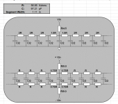
I plan to use the number resistors as laid out below. It's a 10 segment panel:
(none/1ohm Pri),(4),(4),(4),(3),(3),(3),(2),(2),(2)
Does this look good?
So reading over everything carefully again, I remember I had my panel resonance at around 124hz (after some heat treatment). This is why I can't even conceive of crossover over below 300hz (even that's pushing my luck). Thus is also why I came up with resistor segment value of ~50 kOhm.
So I decided to shoot for 54 kOhm.
Note for my 2nd segment I am look at .75R of ~40kOhm. I may adjust that a big if they are too bright.
My resistors are 2W. Only concern here is do I have enough resistors in the segments to dissipate the heat.
I plan to use the number resistors as laid out below. It's a 10 segment panel:
(none/1ohm Pri),(4),(4),(4),(3),(3),(3),(2),(2),(2)
Does this look good?
If you are measuring a single physical segment, that sounds about right. For best accuracy, tie all segments together to measure the whole panel at once. The higher capacitance value will minimize the overall percentage of the unknown parasitic capacitances mattstat mentioned. But, it is not a necessary measurement unless you are just curious.Oh, I measured again front to back stator segments and I get about 40 pF across the segments...
Yes, it is roughly the correct value for the top octave, so a reasonable value to use when assessing the HF resonance frequency. In reality, the capacitance is continuously changing with frequency. I recently posted a plot showing the variation in capacitance with frequency for a segmented ESL. The capacitance values are larger than yours since the panel was bigger, but the trend should give you an idea what is going on. See attachment # 2 here: Impedance vs. frequency of ESL vs freq response... looking at your test results for my transformers you so very kindly did long ago, I noticed the panel capacitance (Cesl) is shown as 120 pF in the "config 2 planned use", is this correct? I can't remember all the details surrounding this but it seemed right at the time
More details in Post #289.
Yes, that should be plenty of heat dissipation capability.My resistors are 2W. Only concern here is do I have enough resistors in the segments to dissipate the heat. I plan to use the number resistors as laid out below. It's a 10 segment panel: (none/1ohm Pri),(4),(4),(4),(3),(3),(3),(2),(2),(2)
Does this look good?
Thanks for double checking that. As usual, much appreciated.
I was working on the bias supply last night.
I got it working it seems, at least from the arcing... If you recall, I am using CCFL inverter to feed a cockcroft step up ladder. The input is 12 VDC (max), output is 900VAC max @ 40kHZ (I measured it on my oscilloscope, at a much lower voltage obviously ).
I'm planning on using 5X multiplier so I can go up to ~4500V if need be.
Do I need to worry about the ripple coming out of the other side of this? Should I put a filter cap across the output? If so, any guess on what size/type would be best?
Probably going to design a PCB for this bias supply. If I can fight thru the rage of trying to get fritizing to work correctly; I'll post the gerber files for anyone else to use. It's amazingly cheap and easy to send a PCB for manufacture overseas. Oh, and if anyone has a better suggestion for a free-ish PCB design tool than fritzting - I'm all ears
Also going to see about making a high voltage probe. It'd be nice to measure the voltage levels to make sure they are what they are supposed to be. With my 600V, 10Mohm impedance DVM - a 9X chain of well insulated, 10Mohm resistors would give me the ability to measure 6000V - if I've math'ed it right.
I was working on the bias supply last night.
I got it working it seems, at least from the arcing
... If you recall, I am using CCFL inverter to feed a cockcroft step up ladder. The input is 12 VDC (max), output is 900VAC max @ 40kHZ (I measured it on my oscilloscope, at a much lower voltage obviously ). I'm planning on using 5X multiplier so I can go up to ~4500V if need be.
Do I need to worry about the ripple coming out of the other side of this? Should I put a filter cap across the output? If so, any guess on what size/type would be best?
Probably going to design a PCB for this bias supply. If I can fight thru the rage of trying to get fritizing to work correctly; I'll post the gerber files for anyone else to use. It's amazingly cheap and easy to send a PCB for manufacture overseas. Oh, and if anyone has a better suggestion for a free-ish PCB design tool than fritzting - I'm all ears
Also going to see about making a high voltage probe. It'd be nice to measure the voltage levels to make sure they are what they are supposed to be. With my 600V, 10Mohm impedance DVM - a 9X chain of well insulated, 10Mohm resistors would give me the ability to measure 6000V - if I've math'ed it right
.- Status
- This old topic is closed. If you want to reopen this topic, contact a moderator using the "Report Post" button.
- Home
- Loudspeakers
- Planars & Exotics
- About to take the ESL plunge