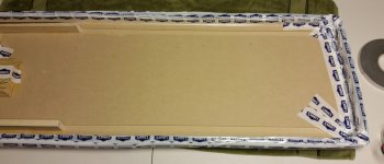
Quick update... So I "reworked" my vertical stretching jig into a inner tube type jig.....and believe it or not the 32" walmart tube fits!
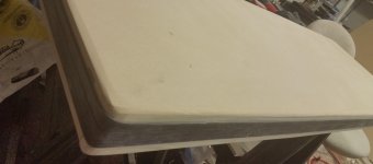
The dimensions of the table are 54.5" X 18.5". I have to stay it was quite a stretch to get it on there and I doubt you could go much bigger (MAYBE another 1" each way). I also rounded over the corners and rounded over all the edges.... AND sanded the whole thing. I plan to put that tape Charlie used over the edges and wax it to help the mylar to slide.
Not entirely convinced this thing is going to work since the tube is much tighter going around the corners of the table than the sides. Also, you have to careful to "even out" the stretch of the tube all around the table as the corners will tend to hold it and keep one side tighter than the other.
But hope springs eternal and since it has worked for others, I have to believe it will work for me 🙂
I've attached a couple of pictures, they aren't the greatest but you get the idea.
I'll post an update when I get the mylar on it and fill it with air.
Attachments
I hope your going to inflate the tube as a trail run before doing the real thing with the mylar so you can help get even expansion all the way around and even more importantly post some photos for us of the expanded tube 🙂
You might be able to get the tight corners to expand more using a heat gun on them.
You might be able to get the tight corners to expand more using a heat gun on them.
Hi Bengel
You worry me when you say you sanded the thing. Stretched mylar is quite fragile, and the small spikes of wood or plastic caused by sanding are enough to puncture the mylar and cause it to tear.
Clean glass is good.
R
You worry me when you say you sanded the thing. Stretched mylar is quite fragile, and the small spikes of wood or plastic caused by sanding are enough to puncture the mylar and cause it to tear.
Clean glass is good.
R
Quick update... So I "reworked" my vertical stretching jig into a inner tube type jig.....and believe it or not the 32" walmart tube fits!
The dimensions of the table are 54.5" X 18.5". I have to stay it was quite a stretch to get it on there and I doubt you could go much bigger (MAYBE another 1" each way). I also rounded over the corners and rounded over all the edges.... AND sanded the whole thing. I plan to put that tape Charlie used over the edges and wax it to help the mylar to slide.
Not entirely convinced this thing is going to work since the tube is much tighter going around the corners of the table than the sides. Also, you have to careful to "even out" the stretch of the tube all around the table as the corners will tend to hold it and keep one side tighter than the other.
But hope springs eternal and since it has worked for others, I have to believe it will work for me 🙂
I've attached a couple of pictures, they aren't the greatest but you get the idea.
I'll post an update when I get the mylar on it and fill it with air.
the fact it is tight around the corners is perfect !! because this is where mylar rips since you cant stretch the corners as much as the rest. i had to pump it up ad piece of tape over the corners before i could pump it up to the desired tension from the quad esl63, if i did not do this 3micron wont survive !
Hi Bengel
You worry me when you say you sanded the thing. Stretched mylar is quite fragile, and the small spikes of wood or plastic caused by sanding are enough to puncture the mylar and cause it to tear.
Clean glass is good.
R
The top of the table is MDF, so it is pretty smooth. I attempted to do a stretch last night and it failed but that was without the polyester tape over the edges. The polyester tape doesn't stick to the MDF hardly at all. That was after wiping everything down with alcohol to get dust etc off of it. I am going to try the tape used to patch rips in vapor barrier next.
The tube without mylar inflates pretty evenly so no concern about it "bulging" unevenly.
As others have noted, I did find using an air compressor makes it difficult the control the stretch precisely. Probably will switch to a hand pump or one of those tiny inflator pumps that plug into your car's cigarette lighter.
One design flaw with the jig is the width of my table combined with the "height" of it means the mylar I have isn't wide enough to wrap completely underneath the table on both sides. So I had to put double sided tape down one the side of the table rather than wrap it under. Didn't seem to be a problem holding it down but if it gets to be a problem, I will cut down the height with my table saw (which will be an adventure).
A few pointers borne from experience:
If possible round the 4 corners a bit more
Position the tube closer to the top surface
If possible trim the height to allow wrapping the film onto the underside.
When you cut the film off the roll, use very sharp scissors to make a smooth straight cut-- the film is very fragile and any nicks on a trimmed edge will provide a weak spot for a tear to start when wrapping the film onto the jig.
Layout the film on a beach towel, then invert the jig onto the film and tape in place, and then turn the jig upright. You will need to hang the jig over the edge of the worktable to connect the air hose.
You won't get as much stretch at the 4 corners so you must pull out ALL slack there. The film will bunch up at the corners--use polyester tape pulled over the corners to take out the slack.
If you get a tear in the film when wrapping it over the jig, you can patch the
tear with tape if it's outside of the stator area. I had to do this once when I had no more film left on the roll... it saved the day.
Last edited:
Rather than scissors or knives, use a soldering iron to cut the mylar. The melted edge is more resistance to tears.
Rather than scissors or knives, use a soldering iron to cut the mylar. The melted edge is more resistance to tears.
I never thought of that... thanks for the tip!
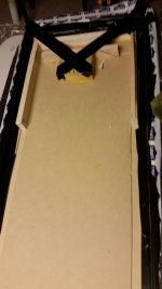
Damn... failed again 🙂.
Oh well, going to make a few more mods to the jig. The tears seem to start on the bottom side of the rails.
BTW, the vapor barrier tape worked quite well, stuck right to the MDF.... put some wax on it for good measure
Oh well, going to make a few more mods to the jig. The tears seem to start on the bottom side of the rails.
BTW, the vapor barrier tape worked quite well, stuck right to the MDF.... put some wax on it for good measure
Attachments
Last edited:
Damn... failed again 🙂.
Oh well, going to make a few more mods to the jig. The tears seem to start on the bottom side of the rails.
BTW, the vapor barrier tape worked quite well, stuck right to the MDF.... put some wax on it for good measure
try to put tape over the corners, after you stretched it half way or bit more.
then it wont snap, it snaps near the corners. i had the same
I think you can help the situation by rounding the 4 corners of your jig a bit more, if you can.
BTW, what is your target elongation (%) for the stretch?
BTW, what is your target elongation (%) for the stretch?
Last edited:
I'm shooting for 1.6%.... erring on the side of having a bit more than a bit less.
I will try rounding the corners a bit more but don't think I can go too much more.
I will try rounding the corners a bit more but don't think I can go too much more.
Fail continues.....
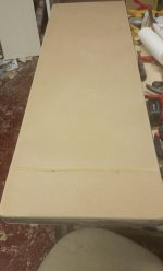
I cut down the table height so I can get a full underneath wrap..... rounded over all edges with a 1/2" round over in my router....
It isn't snapping near the corners anymore. It is literally snapping in a parallel line with the long edge of the table. I will try taping the long edges down and "higher" up and try again.
I put my marks 10" apart so I am looking to come in some where between 2/16"'s and 3/16"'s. I can get to 2/16"'s (1/8") comfortably but when I try to get that little extra it snaps.
Keep trying, until I run out of mylar I guess 🙂
The most I've ever stretched a diaphragm is 1.5% so you're breaking new ground (pardon the pun). My first thought was that 1.6% elongation was too much but then again your panels are much wider than mine-- I'm thinking the max span between supports on your panel is over 5" (is that right?).
On my current panels the diaphragms are stretched to 1.25% elongation, which is plenty for the 3.25" span between supports.
My very first panels were stetched to just 1% elongation and that proved to be adequate for the 3.25" span. On a later panel of similar sized I pushed it to 1.5% and the resulting resonance was higher and forced me to raise the crossover frequency.
Unfortunately, I don't have any data that correlates % stretch to the span and resulting resonance frequencies. That would be great data to have!
It's about 4.5" between supports.
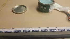
I may just have to settle for what I can get. It takes an insane amount of tape to just hold the mylar down... that is on top of the double sided tape I run along perimeter.....which is almost useless but does provide some foam backing to ease the mylar over the edges.
The lowes tape you see wraps about half up the sides (covering about 1/2 of the inner tube).
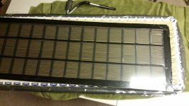
With all of that, I can get it to this point shown in the picture. Basically I put marks 10" apart on the table itself, then after the mylar was put on, I marked over those marks.... so you can see the stretch. I get good stretch in width but not so much in height.
I may just have to settle for what I can get. It takes an insane amount of tape to just hold the mylar down... that is on top of the double sided tape I run along perimeter.....which is almost useless but does provide some foam backing to ease the mylar over the edges.
The lowes tape you see wraps about half up the sides (covering about 1/2 of the inner tube).
With all of that, I can get it to this point shown in the picture. Basically I put marks 10" apart on the table itself, then after the mylar was put on, I marked over those marks.... so you can see the stretch. I get good stretch in width but not so much in height.
Attachments

Just an off-the-wall question and a comment, mostly because I don't know why or how your 1.6% elongation figure was arrived at:
With that much tensioning, do you happen to know what the resonant frequency would/will be?
When I was stretching the mylar for my curved set, I broke it a couple times, and this was a proposed 1.5% elongation.
I then stretched it to just below the breaking point in open air, and discovered the resonance was ~200Hz (using an acoustic guitar tuner).
This was before it would have been a lot shorter on the actual panel, which would have been an even higher frequency..
Guessing around 325-375Hz if that amount of tension would have been placed on the actual (shorter) panel.
(think of a given string tension on an instrument, fretted would be higher yet for same tension)
I ended up not putting near as much tension before final assembly, more like .9-1%
Further reading is here: http://www.diyaudio.com/forums/plan...ut-stretch-your-full-range-esl-diaphragm.html (that's for 'full range' but it's a good read anyway)
Just throwing this out there, food for thought.
Any way to test this before adhesion?
*edit* Disregard this post if I'm missing pertinent information
Last edited:
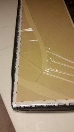
So update.... I finally had success tonight stretching and attaching the membrane to the stator panel.
I got something like a 1.5% stretch.... however I strongly suspect the stretch is tighter in the middle than the ends of the panel judging from how the bike tire was inflated.
As you can see, I got my stretch horizontally and not so much vertically (which is what I believe I was want anyways with my vertical spacers).
I gave up on the double sided tape and instead I taped the bottom perimeter of the mylar with the lowes tape (I believe it is tyvek tape) for reinforcement and then used gorilla tape that sticks to that and to the MDF underside of the jig.
I inflated the tube a bit to get the wrinkles out and put a little stretch in it... At that point, I put some of the lowes tape over top of the mylar in the corners (top side) - to reinforce it. Then I inflated it to its final stretch.
It may be a little tighter than I want but I figured the tape (UHB BTW) would relax a little over time and if it is really a problem I could heat gun it to loosen it up.
Per Sanders advice in his book, I wanted to err on the higher side of a stretch % for my hybrids.
I may get frisky and try testing the resonance frequency to make sure it is reasonable before I stick it all together.
One more to go, then coating, then charging ring.... 🙂
I'm going to have a drink now......
Attachments

Last edited:
The most I've ever stretched a diaphragm is 1.5% so you're breaking new ground (pardon the pun). My first thought was that 1.6% elongation was too much but then again your panels are much wider than mine-- I'm thinking the max span between supports on your panel is over 5" (is that right?).
On my current panels the diaphragms are stretched to 1.25% elongation, which is plenty for the 3.25" span between supports.
My very first panels were stetched to just 1% elongation and that proved to be adequate for the 3.25" span. On a later panel of similar sized I pushed it to 1.5% and the resulting resonance was higher and forced me to raise the crossover frequency.
Unfortunately, I don't have any data that correlates % stretch to the span and resulting resonance frequencies. That would be great data to have!
This is some very good information Charlie, thanks. Just wondering what you had to increase your crossover frequency to when you pushed it to 1.5%, and also what crossover frequency you are running on your current panels. I think Roger Sanders on his current model is running 172.5HZ? I realize though he is not doing a segmented panel, not sure if that makes a difference. Thanks, Neil
So update.... I finally had success tonight stretching and attaching the membrane to the stator panel.
I got something like a 1.5% stretch.... however I strongly suspect the stretch is tighter in the middle than the ends of the panel judging from how the bike tire was inflated.
As you can see, I got my stretch horizontally and not so much vertically (which is what I believe I was want anyways with my vertical spacers).
I gave up on the double sided tape and instead I taped the bottom perimeter of the mylar with the lowes tape (I believe it is tyvek tape) for reinforcement and then used gorilla tape that sticks to that and to the MDF underside of the jig.
I inflated the tube a bit to get the wrinkles out and put a little stretch in it... At that point, I put some of the lowes tape over top of the mylar in the corners (top side) - to reinforce it. Then I inflated it to its final stretch.
It may be a little tighter than I want but I figured the tape (UHB BTW) would relax a little over time and if it is really a problem I could heat gun it to loosen it up.
Per Sanders advice in his book, I wanted to err on the higher side of a stretch % for my hybrids.
I may get frisky and try testing the resonance frequency to make sure it is reasonable before I stick it all together.
One more to go, then coating, then charging ring.... 🙂
I'm going to have a drink now......
I'll drink to this later tonight..😀 Success is sweet isn't it? 🙂
The testing doesn't have to be anything elaborate, you could even do it with your voice starting with the lowest notes and gradually raising your voice (or use sweeps through a woofer near the panel), when the main resonance is reached, it will be obvious. For reference, an open A string on a guitar is 440Hz. BTW, my fret analogy was flawed, sorry.
I didn't go back over the thread to find out, so what is the H & W of your panel again? And do you recall how much material (wire/rods) you needed for 4 stators? Rough cost estimate for whole project?
I really should go back over the thread and take some notes, see if I'm missing anything (sure of it 😱)
Thanks, and congrats!
 Couple more laps and...
Last edited:
- Home
- Loudspeakers
- Planars & Exotics
- About to take the ESL plunge