Could you not just cut the frame down and attach them with glue/screws? Maybe add support at the outsides if needed?Ok, my ceiling is ok for the pair stacked. So if I understand correctly I'll need a serious wood work to built the 8 slot frames. Is there a project somewhere from I can start from? May be just for asking my woodworker for a quote.
Ultimately, it all depends on how much work you want to do, how much you want to spend, and how you want them to look. Many possibilities and variations of execution. But since you won't have the proper LF transformers for an 8-panel system, I suggest you try it out before investing too much.
Hi, I own a pair of 2+2 speakers in Tucson AZ. I recently vacuumed the panels and had the mk 121 blue medallion interfaces rebuilt because the left speaker had low output. They are now arcing quite a bit. At idle you can hear a static pop every once in awhile from either speaker and during passages with deeper bass, there is a static sound. The man who rebuilt my interfaces said he added one stage to each of them to get to 3.2kv. Do you think that the extra stage is making them arc?
Your speaker may have issues with low diaphragm tension, or dirt caught in the gap. BUT, increasing the bias voltage will certainly aggravate these issues, and I do NOT recommend this practice of increasing bias voltage above original design specifications. Doing so is asking for trouble. I suggest you have the extra stage removed and the circuit returned to its original configuration. Then see if you still have a problem.
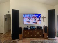
Thank you so much for your advice!! I removed the extra stage and now experience zero arcing at idle or during loud passages! Attached is a picture of my stereo. I’m now removing the ProAc speakers as they sound silly compared to the 2+2.Your speaker may have issues with low diaphragm tension, or dirt caught in the gap. BUT, increasing the bias voltage will certainly aggravate these issues, and I do NOT recommend this practice of increasing bias voltage above original design specifications. Doing so is asking for trouble. I suggest you have the extra stage removed and the circuit returned to its original configuration. Then see if you still have a problem.
Attachments
Hello again, I'm close to buy the second pair of model 4 for this 4+4 project but as you said I don't have the proper LF trafo so I'll add a processor to manage the 4 channels, but still not sure if at the end the final result will be better or worst than an original 8 panel speakers set...Ultimately, it all depends on how much work you want to do, how much you want to spend, and how you want them to look. Many possibilities and variations of execution. But since you won't have the proper LF transformers for an 8-panel system, I suggest you try it out before investing too much.
I'm the fortunate original owner of a pair of Spectra 3 speakers that have worked perfectly for 40 years. During the past few years one of them has slowly lost output. As the bias voltage measures approximately 4.5 KV my guess is accumulated crud in the panel. I'm planning to rebuild the bias networks anyway but I have some questions about the MK-200-3 interface.
- Does anyone have a schematic for it?
- It looks like there are 3 non-polar electrolytics in the filter networks but two of them are tightly sandwiched between the mounting panel and the lower circuit board. Was there an equivalent to the C-mod for this interface?
I don't believe there was a published schematic for the original hybrid Spectra 2 or 3. However, schematics for later non-hybrid Spectra 22/33/2200/3300 are exactly the same for the ESL portion. The electrolytic capacitors you see are for the crossover when using the speaker in the hybrid mode. There is no equivalent Medallion upgrade for the Spectra series. Lessons learned from the Medallion improvements were incorporated in the Spectra series.
I would rebuild the bias supplies as your first step - this is the most common cause of low output. Replace all five diodes and five capacitors in the bias multiplier with equivalent parts. Resist the urge to upgrade the bias supply - there is no sonic advantage. Suggestions for replacement parts have been posted previously.
Does your speaker use the line-cord power supply, or is it powered by a wall transformer?
Thank you for that information. Before replacing any suspect parts I wanted to verify that there was no "C-mod" or other design change that might use different values.
In addition to rebuilding the bias networks, which are the old style with a step-up mains transformer, the 500M resistor will also get replaced. Surprisingly, the one in the interface that I'm currently working on measures about 30% high!
I've read all of the responses in this forum and have learned a great deal. Many thanks for both your original contributions to Acoustat speakers and your patient assistance to those of us who endeavor to keep them running in peak form.
Unfortunately, my speaker problem is an open secondary winding in one of the transformers. They are marked XS203 and 2009273. Does anyone know of a source for repair or replacements? Are the transformers from other models interchangeable other than different color codes?
I'm sorry, I am not aware of any sources for the Spectra transformer. Models Spectra 2, 22, 2200, 3, 33 and 3300 all use the same audio step-up transformer. The transformer used in Models 44, 4400, 66 and 6600 are NOT the same.
There is no equivalent "Medallion" or "C-Mod" upgrades for the Spectra series.
There is no equivalent "Medallion" or "C-Mod" upgrades for the Spectra series.
Using a Spectra 1100 or 2 /22 /2200 interface, is it possible to turn a 1+1 into a Spectra 1+1?
The idea is to create the narrowest HF section, full height, for better dispersion.
The Spectra 1100 schematic shows 3 sections:
Woofer (hybrid setup)
Mids
Mids and Highs
Resistors might have to be changed.
I'd use a very tight clean subwoofer for the bottom end.
Brandon
The idea is to create the narrowest HF section, full height, for better dispersion.
The Spectra 1100 schematic shows 3 sections:
Woofer (hybrid setup)
Mids
Mids and Highs
Resistors might have to be changed.
I'd use a very tight clean subwoofer for the bottom end.
Brandon
You're going to have to split the stator wires in the appropriate location at one end of each panel and run an extra wire. While you're doing that, you may as well convert to the later 5-wire type by adding wire to the free ends of each section as well and joining them to the associated existing wires.
- Home
- Loudspeakers
- Planars & Exotics
- Acoustat Answer Man is here