As mentioned by another poster, panels would need to be converted to “Spectra style” by splitting the front and rear stators. This is not easy, but possible if you already have 5-wire panels. If you have 3 -wire panels, an additional outfeed wire would need to be added to each panel. This is considerably more difficult.
There are no existing transformers that are ideally suited to this arrangement. I would recommend using the transformers from Spectra 11 or 1100, using two per speaker (one for each panel). These transformers (and their accompanying RC outfeed network) are designed to drive only one panel. You could use a common bias supply for both panels.
Such an arrangement would require a companion woofer, crossing over in the 150-200 HZ region, to match the inherent roll-off of the transformers. Due to the higher crossover point, a stereo pair of woofers would be the best solution. Do not try driving these transformers full-range – they are not designed for it and will saturate at low frequencies.
Using transformers from the full-range Spectra would be difficult, if not possible. These transformers are designed to drive three segments of the ESL, and in a 1+1 configuration, you’d have only two segments available. I offer this statement only to explain why I would not recommend this approach.
This is a product I always wanted to make, due to the popularity of the original 1+1. I envisioned a hybrid speaker, using one woofer per speaker, and using a (single) modified version of the Spectra 11/1100 transformer (i.e., one that was designed to drive two panels). But alas, Acoustat went away before we were able to introduce such a product. Another dream down the tubes.
This is an interesting project - let me know if it comes to fruition!
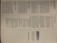
I received a private request for the Acoustat White Paper. Believing that everything Acoustat should be shared equally, I am re-posting here in the public forum. Both the original and Spectra versions are attached.
Attachments
Hello all, a brand new poster here but not brand new to Acoustats. I have been happily owned by 1+1’s, 2+2’s and now model X’s. I’m hoping to get some advice on an issue with one of the amps. I have been slowly replacing parts and have gotten some fair results but still not up to the performance of the other amp.
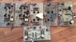
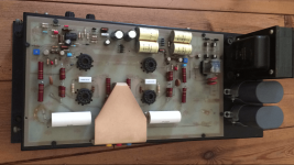
Symptoms as of now after some fixed: hiss/noise at idle, muted high frequencies, valve 1 plate glowing red (new 10k resistors should fix) but muted high frequencies and noise, slightly less volume are the issues I can’t find yet.
Replaced so far: bias diodes (fixed loud hum), all plug in transistors replaced with new Motorola’s, bias caps tested good, valves tested good. Thanks for any advice!
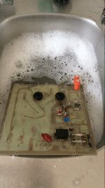
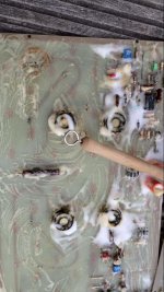
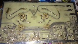
The original high voltage resistors need to be checked as these loose contact from arcing over time. Red cheek on all tubes or some (upper or lower). Please do not use more powerfull resistors for the 10k values as these can act as fuses in case things go bad. Also make sure that these are off the board not to grill the board in case these get hot. The resistors can be replaced not so the board.
Make sure you switch speakers during testing to rule out panel issues.Hello all, a brand new poster here but not brand new to Acoustats. I have been happily owned by 1+1’s, 2+2’s and now model X’s. I’m hoping to get some advice on an issue with one of the amps. I have been slowly replacing parts and have gotten some fair results but still not up to the performance of the other amp.
Symptoms as of now after some fixed: hiss/noise at idle, muted high frequencies, valve 1 plate glowing red (new 10k resistors should fix) but muted high frequencies and noise, slightly less volume are the issues I can’t find yet.
Replaced so far: bias diodes (fixed loud hum), all plug in transistors replaced with new Motorola’s, bias caps tested good, valves tested good. Thanks for any advice!
In some cases the board itself can become conductive, in that case it needs to be stripped and cleaned.
Attachments
-
 59598-1c79a83e40c3850d3c721377adb0061f.png357.4 KB · Views: 130
 -
 59597-0c7072b632fdb1e21a4dece17857bce6.jpg99.4 KB · Views: 119
 -
 59599-e5a7515b2f34fadad5f2312c736dc160.jpg99.4 KB · Views: 130
 -
 59601-888f7540f83e0227735f405addb9acf2.png340.9 KB · Views: 127
 -
 59600-ffc1c4bb9298b3d64bb3ab6c90139eca.jpg103.5 KB · Views: 130
 -
 59602-f2279ce1e309bf3f37fff57271c54035.jpg233.4 KB · Views: 129
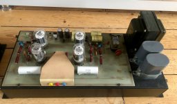
Ok, I seemed to have solved the issue of V1 plate glowing excessively and the hiss at idle. I replaced R38 (10k 15 watt) and R39 (470 k) not sure which one did it. I still have reduced volume, high frequency attenuation, distortion at higher volumes and an overall vailed sound compared to the “good side”. The good side is completely amazing with tremendous volume and clarity with a ridiculously quiet noise floor.
I have rolled tubes and swapped panels and sources/cables with the existing problems always following the amp.
Thanks for anymore input!
I have rolled tubes and swapped panels and sources/cables with the existing problems always following the amp.
Thanks for anymore input!
Bummer. They probably both need complete overhaul. Especially so they both perform identically.
As mentioned by another poster, panels would need to be converted to “Spectra style” by splitting the front and rear stators. This is not easy, but possible if you already have 5-wire panels. If you have 3 -wire panels, an additional outfeed wire would need to be added to each panel. This is considerably more difficult.
There are no existing transformers that are ideally suited to this arrangement. I would recommend using the transformers from Spectra 11 or 1100, using two per speaker (one for each panel). These transformers (and their accompanying RC outfeed network) are designed to drive only one panel. You could use a common bias supply for both panels.
Such an arrangement would require a companion woofer, crossing over in the 150-200 HZ region, to match the inherent roll-off of the transformers. Due to the higher crossover point, a stereo pair of woofers would be the best solution. Do not try driving these transformers full-range – they are not designed for it and will saturate at low frequencies.
Using transformers from the full-range Spectra would be difficult, if not possible. These transformers are designed to drive three segments of the ESL, and in a 1+1 configuration, you’d have only two segments available. I offer this statement only to explain why I would not recommend this approach.
This is a product I always wanted to make, due to the popularity of the original 1+1. I envisioned a hybrid speaker, using one woofer per speaker, and using a (single) modified version of the Spectra 11/1100 transformer (i.e., one that was designed to drive two panels). But alas, Acoustat went away before we were able to introduce such a product. Another dream down the tubes.
This is an interesting project - let me know if it comes to fruition!
Regarding: "is it possible to turn a 1+1 into a Spectra 1+1?"
See Posts 3018 - 3021 (to top of this page)
Thank you Andy. And thanks for the Spectra white paper.
I am trying to reduce the trial and error time:
1. If you use two interfaces per channel your amp is going to see half the impedance so it would need to be happy down to around 2 ohms. That eliminates most amps.
Or you would have to double your amp channels, one for each panel, with amps that are happy at or slightly below 4 ohms.
2. Maybe you could use a single full range Spectra interface, if you fed the third section into a dummy load resistor.
But I don't know panel section impedance to calculate the resistor?
3. In any case I think you are going to have to play with the resistor values to the sections.
4. How narrow could you make the treble (full-range) section and still get enough HF output?
Could you divide each 1+1 panel into three sections?
Brandon
Hi Andy, new member here and I have a question. I found a local tech to replace all the degrading parts of the interfaces om my vintage model 2MH Acoustats, but before disconnecting to remove the interfaces, is there a need and a procedure to discharge the panels (or anything else)? Many thanks in advance!
The speaker does retain a charge after being unplugged from AC power. The simplest way around this is to let the speaker sit for 24 hours after unplugging. Another quicker method, which may be difficult on the 2MH, is to unplug the speaker from AC, and then detach the red pin-plug from the interface and touch its tip to either the adjacent white or blue binding posts. Be sure not to touch any parts of the circuit while doing so.
If I may a somewhat, but short, OT question - the HV / drive circuit for an electrostatic, is there a dimensioning aspects tied to the size of a panel?
I'm thinking of getting a pair of (some brand) electrostatic and use the electronics to drive a (fairly big) DIY panel of mine...
//
I'm thinking of getting a pair of (some brand) electrostatic and use the electronics to drive a (fairly big) DIY panel of mine...
//
It doesn’t depend on size but load (capacitive load that is) and the voltage you need to drive yours as this had to do with the distance of the stators to the foil. Now in case this is a shorter distance in yours you could get arcing if the voltage is too high but distortion or low level output if the voltage is too low.

salve a tutti. utilizzo una coppia di 4400 e una di 2+2, con due amplificatori Hafler xl 600. Come posso ottenere omogeneità timbrica dato che i 2+2 sono più frizzanti? Grazie.
Hello everyone. I use a torque of 4400 and one of 2+2, with two Hafler XL 600 amplifiers. How can I get timbre homogeneity since the 2+2 are more sparkling? Thank you.
English please.
dave

diyAudio moderation team
Hi there,
New here! I have a pair of Acoustat 2MH MK-131, exactly like the ones you can see by clicking the link below, even same colour! My concern here is that they are 120v and Where I live we have 220v, so…how big of a transformer do
I need to run the speakers comfortable? 50w, 100w, 200w?? Is there any room in the MK-131 module to fit it in there and then add a panel mount iec connector to the box and use an iec cable to be able to connect them straight to the wall?
Thank you very much!!
Tino
Mains power consumption is minimal, so a 50-watt (or even less) step-down transformer will be fine. I don't recommend trying to mount anything within the speaker - there isn't much room, and distances would need to be maintained from the high-voltage circuits. I would recommend a single, external step-down transformer powering both speakers.
I use a couple of 4400 and a couple of 2+2. How can I have tonal homogeneity? Another question. How can I commute 4400 in 66 given that I've got four additional panels? Thank you to all.
The Spectra 4400 and Model 2+2 are different speakers, using different technologies, so one cannot expect them to sound the same, especially due to their very different dispersion patterns. There are no adjustments on the Spectra 4400 (other than setting the bias voltage correctly), the 2+2 does have a High-Frequency Balance Control, which can be used to modify the extreme top-end response.
The MK2146 interfaces on your Spectra 4400 can also drive six panels with a change to the transformer taps. This is not easy to do, as it requires complete dis-assembly of the interface. But otherwise you can make a 6600 with the addition of 2 extra panels per speaker.
The MK2146 interfaces on your Spectra 4400 can also drive six panels with a change to the transformer taps. This is not easy to do, as it requires complete dis-assembly of the interface. But otherwise you can make a 6600 with the addition of 2 extra panels per speaker.
- Home
- Loudspeakers
- Planars & Exotics
- Acoustat Answer Man is here