Hi Markw4,
I've seen your setup photo but not being as knowledgeable as you guys are, the image alone wouldn't help me much, so thanks for the precisions!
I'll look into it but I was looking for something a bit more ready-to-use with minimal DIY steps for the +-15V.
Regarding the 5V supplies, since we're at it, I was planning to use 3 iPower 5V (Isolator, Katana and MC). I can get those for 50$ tx inc. from a local shop, so given the advertised performance, so unless you guys advise otherwise, I thought that could be a decent price/quality compromise and maybe invest more on the +-15V which seems to be more critical if I understood correctly.
Hi Markw4,
I've seen your setup photo but not being as knowledgeable as you guys are, the image alone wouldn't help me much, so thanks for the precisions!
I'll look into it but I was looking for something a bit more ready-to-use with minimal DIY steps for the +-15V.
Regarding the 5V supplies, since we're at it, I was planning to use 3 iPower 5V (Isolator, Katana and MC). I can get those for 50$ tx inc. from a local shop, so given the advertised performance, so unless you guys advise otherwise, I thought that could be a decent price/quality compromise and maybe invest more on the +-15V which seems to be more critical if I understood correctly.
I'd caution against the iPower. There are a LOT of documented complaints about the quality of those supplies, including frying the devices they power (see: iPhono 2). I've owned iPowers and both had high pitched squeals whenever plugged in, which is also a known issue. I promptly returned them.
I'd caution against the iPower. There are a LOT of documented complaints about the quality of those supplies, including frying the devices they power (see: iPhono 2). I've owned iPowers and both had high pitched squeals whenever plugged in, which is also a known issue. I promptly returned them.
Hey wushuliu,
OMG! Do you think it could have fried my Katana board through J31?
I already had 2 iPower on hands so before getting a third one, I wanted to do a test:
- Isolator: allo provided cheap PSU
- Microcontroller: iPower
- Katana: iPower
When powering Katana board, I saw solid PWR LED on Isolator, no LED on Katana and blinking STATUS LED on MC. Katana is not detected anymore, even reverting to my previous 2 PSU (Isolator + MC) setup.
Still trying to figure out the cause on another thread but I thought it was due to inverted polarity connector I received from allo for J31 on Katana board....
In regard to the paralleled film caps on the ps output, I am not surprised that they would have a positive result. It's a tweak that's been used and discussed over the years. Resurfaces every now and again. Just a question of how far one is willing to go down the rabbit hole. Paralleled film caps in large values aren't exactly compact. Then usually not far into the discussion someone comes along and says STOP its best practice to have electrolytics instead and as close to the board/ICs as possible and that the long wire leads from the cap bank will increase RFI, etc. (AndrewT RIP!)
As for the LT3045/2 I think their mass appeal lies less in their low noise than in their availability in compact, easy to implement form and inexpensive prices. Goodness knows I got my share of Salas power supplies that are probably better, but they're bulkier and take more fiddling and care to assemble and test. I save them for final builds or one and done projects that won't involve constant tinkering.
As for the LT3045/2 I think their mass appeal lies less in their low noise than in their availability in compact, easy to implement form and inexpensive prices. Goodness knows I got my share of Salas power supplies that are probably better, but they're bulkier and take more fiddling and care to assemble and test. I save them for final builds or one and done projects that won't involve constant tinkering.
Last edited:
Hey wushuliu,
OMG! Do you think it could have fried my Katana board through J31?
I already had 2 iPower on hands so before getting a third one, I wanted to do a test:
- Isolator: allo provided cheap PSU
- Microcontroller: iPower
- Katana: iPower
When powering Katana board, I saw solid PWR LED on Isolator, no LED on Katana and blinking STATUS LED on MC. Katana is not detected anymore, even reverting to my previous 2 PSU (Isolator + MC) setup.
Still trying to figure out the cause on another thread but I thought it was due to inverted polarity connector I received from allo for J31 on Katana board....
Yikes. Dunno, but I happen to be reading a long thread on the iPhono 2 today elsewhere and it was one complaint after the other of units having fried boards and not working. As in people actively warning others to stay away. Then I saw that it comes with an iPower and remembered all the complaints over at yet another forum about units that went DOA or made noises, etc. etc. and I put the two together. So I think it's very possible yes. The issues with iPower supplies have been known for several years now.
Hey Greg,
let us know where we can see your updated settings for each combo and how we can get notified once they're available!
Regarding PSU options, I saw you mentioning mpaudio a few times. I know you didn't try it (yet) but do you think it could be a good option for +-15V? If so, here would be my 2 questions:
1- would the smallest unit be sufficient? MPAudio | Produktseite
2- How do you connect it to 120V outlet? Do you still need some PSU? If so, any good affordable suggestion?
@chris14, thanks for the reminder on Allo's promised linear PSU. Hopefully cdsgames will see this and provide an update. AND I bet you are right in that for most, it will be a good single-box solution.
PCB (10 units) will be received in about 10 days for testing. I will post updates but on proto (only one unit) , we get noise..we dont get any noise. Its almost at floor of Audio precision machine. Thats about 0.2uV
0 common mode noise, almost no leaking current
Each rail has big capacitor bank , then active filters , then LDOs , then more active filters and finally big caps + supercaps on the output for very low impedance .
Last edited:
...
Regarding the 5V supplies, since we're at it, I was planning to use 3 iPower 5V (Isolator, Katana and MC). I can get those for 50$ tx inc. from a local shop, so given the advertised performance, so unless you guys advise otherwise, I thought that could be a decent price/quality compromise and maybe invest more on the +-15V which seems to be more critical if I understood correctly.
Probably safer bet to use a linear +5v supply for the Katana stack. An wall wart type IFI or other +5v supply can be used for the lower part of the Isolator board and the RPi together.
Regarding film caps, I locate the banks of film caps close to the +-15v power entry point at Katana and use thick gauge wires. That keeps any ESR concerns to a minimum. However, the +-15v connection pins at Katana are normal pin header pins, so not very big, and then the power is routed down through traces and more connectors to the Katana board where there are more LDOs. The exact ESR from the film caps to Katana as I tested it does not seem particularly critical. The caps just help get rid of the last bit of grainy or rough textured sound from Katana, and makes the analog output noticeably closer to perfect or ideal sounding.
Last edited:
This one might spark a bit of controversy...
First, a reminder to all to be polite and respectful. From the forum rules...
Rule #1. NO Disruptive behavior of any sort, including offensive language, trolling, threadjacking, insults, intimidation, harassment or other disrespectful or antisocial behavior (slightly edited for clarity).
Guideline #1. Do be polite. Even when you don't want to be.
'Tone' is important! Nuff said?
Second, @Jonathan P, I'll post in this thread when I update the first post. I don't think anyone gets automated notifications on that. Good catch.
AND on the MPAudio units as +-15V supplies for a Katana, his small-format supply is designed to be fed with DC voltage, so you need a separate +-16V or higher (I'd recommend 17V-18V) to get +-15V out of the unit. IF you are in the US, an interesting option to consider here are 2 of the Jameco 12V Linear Regulated Adapters as their raw DC voltage is about 19V. It would take at least a minimal modification to open them up and tap off the raw DC before the regulator. There are others out there, sorry I don't have a recommendation off the top of my head.
OTOH, his MD-HPULN PS will only require a transformer as it is designed to take an AC input. If you decide to go that route, I'm sure we can recommend appropriate transformers for you based on your country's ACV.
Third, @cdsgames, thanks for the update your supplies. Looking forward to seeing them and hearing the reports.
Fourth, @Markw4, thanks for providing more info on your add-on cap setup for @Joshua43214. & I'd forgotten to mention the upgrades you did to your +-15V supply kit... those are all worthwhile and I would do the same if I was building one. I DO want to say that the 'grainy or rough textured sound' you heard may not be universal to the Katana, but possibly power supply or system specific. I did not hear any of that with my 'best' setup using separate +-15V supplies. AND I still intend to try a polyprop cap bank on each of the supplies... I've done this a lot over the years and always found it beneficial.
Fifth, @Wushuliu, thanks for the heads-up on the iFi iPower issues. Honestly, I had not seen any of that and it is good to know. AND I'd strongly agree with your comments on the Salas versus the LT3045/42 variants... As I've said earlier in the thread, I suspect a setup powering an RPi -> Isolator 1.2 -> Katana stack with 3 5V & 1 +-15V Salas UltraBiB well-implemented would take the SQ to a level above what I'm already hearing in my system.
Finally, interesting all of the iFi iPower chatter... as that was the first thing in my "audio friend's" recent report. He started his latest trials with the following configuration:
1. No isolator
2. His preferred SMPS on the RPi 3B+ via microUSB (note that this is a small and inexpensive SMPS from Micro Center designed for powering units like the RPi... I'll try to provide a link in a later post)
3. LT3042/Pass Transistor on the micro controller
4. LT3042/Pass Transistor on the DAC
5. Placid HDBP on the I/V and buffer
The first thing he did was sub in an iFi iPower 5V to power the RPi. His comments:
"Bloody awful! Yes, it is quieter but a bunch of information goes away with the “noise" in the process - way, way too much in fact. It becomes dull, life-less, and uninteresting to listen to".
His was a stronger reaction than mine the last time I tried the iFi unit, but I'm totally in alignment... it is not a great supply in my setups and to my ears. At best a good bottom baseline supply, IMHO.
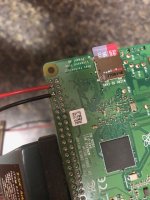
The second thing he did was try 2 different options to feed power into the RPi... either via the Micro USB or via the GPIO header pins (I've attached a picture of how he soldered the power wires onto the RPi header pins). His comments:
"In the past, with the Boss DAC and others, feeding the RPi through the GPIO header from the top sounded much, much better than feeding in through the microUSB connector on the RPi, and I suspected much the same with the Katana. But, as you know, there’s no access to the header from the top with the Katana.
So, I soldered a couple wires on the power and ground pins on the bottom of the 40-pin GPIO header on the RPi 3B+.
Upon listening, I have to say, the difference in feeding power wasn’t anywhere near what I had experienced in the past with other DACs. In fact, at this point, I could have gone either way on feeding power to the RPi, although there was a bit of a preference for the soldered connection.
Please note, many previous comparisons were with the 3B and not the 3B+. Still, I think the protection circuitry on the other side of the microUSB
connector is pure evil from an audio perspective. So, I ran through the SMPS and the iFi again, finding the same."
The third thing he tried was a another power supply to the RPi:
"Having satisfied myself on how best to feed power to the the RPi, I then tried a linear bench/lab supply now having a couple of wires to easily connect to. All I can say is WOW! This is a game changer. I’ve tried all sorts of supplies on the RPi in the past and this is the first time where I thought the difference with a linear supply was warranted and …. Well, you just HAVE to do it. With the current set up, it is as big a difference as anything to me. I’m committed to building a dedicated supply here."
Finally, he put in the Isolator 1.2 and had this to say:
"...I then introduced the isolator. Unlike my experience with the Boss DAC, I detected no initial detriment to the sound. Just, lower noise and blacker,
much as you describe. Again, I ran through the various supplies on the RPi just to be sure, finding the same. I also ran through a couple different regulators on the micro controller and the DAC, likewise confirming my preferences there without the isolator."
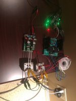
I've also added a photo of his setup as it is now.
I'll end with apologizing that my reports are nowhere near as measured, complete, and thorough as his!
Greg in Mississippi
First, a reminder to all to be polite and respectful. From the forum rules...
Rule #1. NO Disruptive behavior of any sort, including offensive language, trolling, threadjacking, insults, intimidation, harassment or other disrespectful or antisocial behavior (slightly edited for clarity).
Guideline #1. Do be polite. Even when you don't want to be.
'Tone' is important! Nuff said?
Second, @Jonathan P, I'll post in this thread when I update the first post. I don't think anyone gets automated notifications on that. Good catch.
AND on the MPAudio units as +-15V supplies for a Katana, his small-format supply is designed to be fed with DC voltage, so you need a separate +-16V or higher (I'd recommend 17V-18V) to get +-15V out of the unit. IF you are in the US, an interesting option to consider here are 2 of the Jameco 12V Linear Regulated Adapters as their raw DC voltage is about 19V. It would take at least a minimal modification to open them up and tap off the raw DC before the regulator. There are others out there, sorry I don't have a recommendation off the top of my head.
OTOH, his MD-HPULN PS will only require a transformer as it is designed to take an AC input. If you decide to go that route, I'm sure we can recommend appropriate transformers for you based on your country's ACV.
Third, @cdsgames, thanks for the update your supplies. Looking forward to seeing them and hearing the reports.
Fourth, @Markw4, thanks for providing more info on your add-on cap setup for @Joshua43214. & I'd forgotten to mention the upgrades you did to your +-15V supply kit... those are all worthwhile and I would do the same if I was building one. I DO want to say that the 'grainy or rough textured sound' you heard may not be universal to the Katana, but possibly power supply or system specific. I did not hear any of that with my 'best' setup using separate +-15V supplies. AND I still intend to try a polyprop cap bank on each of the supplies... I've done this a lot over the years and always found it beneficial.
Fifth, @Wushuliu, thanks for the heads-up on the iFi iPower issues. Honestly, I had not seen any of that and it is good to know. AND I'd strongly agree with your comments on the Salas versus the LT3045/42 variants... As I've said earlier in the thread, I suspect a setup powering an RPi -> Isolator 1.2 -> Katana stack with 3 5V & 1 +-15V Salas UltraBiB well-implemented would take the SQ to a level above what I'm already hearing in my system.
Finally, interesting all of the iFi iPower chatter... as that was the first thing in my "audio friend's" recent report. He started his latest trials with the following configuration:
1. No isolator
2. His preferred SMPS on the RPi 3B+ via microUSB (note that this is a small and inexpensive SMPS from Micro Center designed for powering units like the RPi... I'll try to provide a link in a later post)
3. LT3042/Pass Transistor on the micro controller
4. LT3042/Pass Transistor on the DAC
5. Placid HDBP on the I/V and buffer
The first thing he did was sub in an iFi iPower 5V to power the RPi. His comments:
"Bloody awful! Yes, it is quieter but a bunch of information goes away with the “noise" in the process - way, way too much in fact. It becomes dull, life-less, and uninteresting to listen to".
His was a stronger reaction than mine the last time I tried the iFi unit, but I'm totally in alignment... it is not a great supply in my setups and to my ears. At best a good bottom baseline supply, IMHO.
The second thing he did was try 2 different options to feed power into the RPi... either via the Micro USB or via the GPIO header pins (I've attached a picture of how he soldered the power wires onto the RPi header pins). His comments:
"In the past, with the Boss DAC and others, feeding the RPi through the GPIO header from the top sounded much, much better than feeding in through the microUSB connector on the RPi, and I suspected much the same with the Katana. But, as you know, there’s no access to the header from the top with the Katana.
So, I soldered a couple wires on the power and ground pins on the bottom of the 40-pin GPIO header on the RPi 3B+.
Upon listening, I have to say, the difference in feeding power wasn’t anywhere near what I had experienced in the past with other DACs. In fact, at this point, I could have gone either way on feeding power to the RPi, although there was a bit of a preference for the soldered connection.
Please note, many previous comparisons were with the 3B and not the 3B+. Still, I think the protection circuitry on the other side of the microUSB
connector is pure evil from an audio perspective. So, I ran through the SMPS and the iFi again, finding the same."
The third thing he tried was a another power supply to the RPi:
"Having satisfied myself on how best to feed power to the the RPi, I then tried a linear bench/lab supply now having a couple of wires to easily connect to. All I can say is WOW! This is a game changer. I’ve tried all sorts of supplies on the RPi in the past and this is the first time where I thought the difference with a linear supply was warranted and …. Well, you just HAVE to do it. With the current set up, it is as big a difference as anything to me. I’m committed to building a dedicated supply here."
Finally, he put in the Isolator 1.2 and had this to say:
"...I then introduced the isolator. Unlike my experience with the Boss DAC, I detected no initial detriment to the sound. Just, lower noise and blacker,
much as you describe. Again, I ran through the various supplies on the RPi just to be sure, finding the same. I also ran through a couple different regulators on the micro controller and the DAC, likewise confirming my preferences there without the isolator."
I've also added a photo of his setup as it is now.
I'll end with apologizing that my reports are nowhere near as measured, complete, and thorough as his!
Greg in Mississippi
Attachments
AND on the MPAudio units as +-15V supplies for a Katana, his small-format supply is designed to be fed with DC voltage, so you need a separate +-16V or higher (I'd recommend 17V-18V) to get +-15V out of the unit. IF you are in the US, an interesting option to consider here are 2 of the Jameco 12V Linear Regulated Adapters as their raw DC voltage is about 19V. It would take at least a minimal modification to open them up and tap off the raw DC before the regulator. There are others out there, sorry I don't have a recommendation off the top of my head.
OTOH, his MD-HPULN PS will only require a transformer as it is designed to take an AC input. If you decide to go that route, I'm sure we can recommend appropriate transformers for you based on your country's ACV.
If MD-HPULN is worth the price diff with SD-HPULN, I might go for it. I Could get an AC transformer from MPAudio also? I'm in Montreal, Canada, so I guess the 120 AC is the same as is the US.
Not sure this would influence the transformer choice but I use a 10 gauge dedicated 120V line for AMP and Katana, along with an ifi AC iPurifier. I guess I was paranoid of noise contamination from neighbors since I live in a condo. Given all the bad comments about the iPower, maybe I'll get rid of the iPurifier once I choose good supplies based on suggestions in the posts that generate low level of noise on the AC line, in order not to harm my AMP's performance. Anyways, I guess that's another topic...
Finally, he put in the Isolator 1.2 and had this to say:
"...I then introduced the isolator. Unlike my experience with the Boss DAC, I detected no initial detriment to the sound. Just, lower noise and blacker,
much as you describe. Again, I ran through the various supplies on the RPi just to be sure, finding the same. I also ran through a couple different regulators on the micro controller and the DAC, likewise confirming my preferences there without the isolator."
I'm not sure if your audio friend prefers with our without Isolator with his best PSU and modded connections setup. I'm confused by his last sentence: "I also ran through a couple different regulators on the micro controller and the DAC, likewise confirming my preferences there without the isolator."
Do you think he means:
1- he saw the same improvements with the Isolator by doing the mods he did without Isolator but still prefers with Isolator
2- after doing all the mods he did without Isolator, he still prefers the sound without Isolator
Very interesting info here. I am sorry, my post does not relate to Katana per se, since I am planning on using a different RPi HAT. But the plan is to power my RPi 2B and DAC separately using diy supplies, hence the interest here.The second thing he did was try 2 different options to feed power into the RPi... either via the Micro USB or via the GPIO header pins (I've attached a picture of how he soldered the power wires onto the RPi header pins). His comments:
"In the past, with the Boss DAC and others, feeding the RPi through the GPIO header from the top sounded much, much better than feeding in through the microUSB connector on the RPi, and I suspected much the same with the Katana. But, as you know, there’s no access to the header from the top with the Katana.
So, I soldered a couple wires on the power and ground pins on the bottom of the 40-pin GPIO header on the RPi 3B+.
I was just reading about powering the RPi 2B using an external supply a few days ago, and it was suggested (not in an audio application) that one uses the microUSB to include all the protection circuitry because – “The Pi2B has a polyfuse that limits input current to 2A, or a bit less. The recommend PSU for a Pi2B is 2A.” Surely a headless RPi will not be drawing a huge current driving a HAT DAC. If the protection circuitry on the other side of the microUSB connector is pure evil from an audio perspective – would you recommend that I feed my RPi 2B through the GPIO header (like shown above)? Can there be any risks in doing this?
@Ralph G, I know Allo has gotten very good results from their LDO's in the past. Even their initial offering, the Piano DAC series, used LT3042 regulators and they still hold up well against other PCM51x2-based RPi DACs. AND early in the Katana development Allo stated they were incorporating the DC-DC converters to make it easy to power the stack with 1 or more 5V supplies, something that has seemed important to some. OTOH, one breakthrough RPi DAC for me was the Dial AUdio one that requires a +-15V supply. With a good supply (the +-15V output of a Silent Switcher did not qualify as that for me on this DAC), it was a significant step above all of the then-other RPi DACs that used DAC chips with integrated output stages in dynamics, clarity, and overall lifelike presentation. While something like the Katana is another significant step above it, it of course comes at a significant cost differential too. AND back to your comments on your choke-zener-cap shunt, I can get how that could be a good sounding option. Love to get a schematic, if you don't mind... please send a PM. AND back to the Dial DAC... the +-15V shunt regulators I used that worked well also used zener diodes to set the voltage. Sorry, it is a friend's proprietary design and I can't share it, but think of it as a less-complex Salas-styled regulator (also likely not as good as a Salas too). So I know they can be 'good' sounding, if used correctly.
Greg in Mississippi
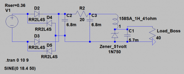
My 5volt Boss supply:
The toroid is a 80VA 12V. Because of the regulation, it generates a bit above 13 volts AC. Times sqrt 2, equals the 18.4 volt used for the simulation.
C2 and C3 are cheap caps. Only C1 is an audio grade (Panasonic). I think I bought a 10 mf (not 5.6).
After the rectifier it is 16 volt DC. R2 is used to finetune the current. After this R2 the DC value is close to 12 volt. And of course on the zener it is the zener value (this 1N750 is 4.9 volt I think, but I used a 5.1 volt zener). The current through the Hammond is 180 mA. The Boss draws about 120 mA (that is where the 40 ohm is coming from). The final PSU worked exactly as simulated.
")
Attachments
Very interesting info here. I am sorry, my post does not relate to Katana per se, since I am planning on using a different RPi HAT. But the plan is to power my RPi 2B and DAC separately using diy supplies, hence the interest here.
I was just reading about powering the RPi 2B using an external supply a few days ago, and it was suggested (not in an audio application) that one uses the microUSB to include all the protection circuitry because – “The Pi2B has a polyfuse that limits input current to 2A, or a bit less. The recommend PSU for a Pi2B is 2A.” Surely a headless RPi will not be drawing a huge current driving a HAT DAC. If the protection circuitry on the other side of the microUSB connector is pure evil from an audio perspective – would you recommend that I feed my RPi 2B through the GPIO header (like shown above)? Can there be any risks in doing this?
twocents,
Let me see if I can help by walking you through how I might attempt to answer the question you presented for myself.
First, from reading the history of the Pi on the Internet, I learned that the Pi was created as a tool to be used use to teach students programming. A means to an end. It was quickly used for many, many things as well - your use as an "audio computer" being one of them. It's just so cheap and easy.
Second, a Google search for the schematic of the RPi2, and here it is:
https://www.raspberrypi.org/documentation/hardware/raspberrypi/schematics/rpi_SCH_2b_1p2_reduced.pdf
Now, look in the upper left hand corner. That's the power portion in question. J1 is the micro USB connector commonly used for connecting power. Next, is F1, the fuse you called out.
Fuses work like fuses, right? But, that's not very helpful. Generally, fuses are used to provide some form of protection - mostly for humans, right? Frankly, if your RPi2 draws sufficient current, e.g., > 2A, for a sufficient amount of time, F1 will blow and you'll have to replace it. And, your RPi2 likely has bigger problems. But, at least you didn't burn the house down or hurt anyone in the process. Remember this was designed for kids to learn.
Now suppose you take F1 out or bypass it by using the header connection. Well, you removed some protection. But, protection could come from elsewhere. For example, the supply you're using with your Pi could include some protection. Some Wallwarts have built in protection. Many regulators shut down in "over current" conditions. Then again, a student might use a high capacity 5 volt battery with a Pi in a robot. As a designer - ya never know.
Ultimately, you have to judge for yourself based on your specific situation. Whether the opportunity for better sound is worth whatever, if any, additional risk eliminating F1. It won't always save your Pi if that's what you're thinking. But, it might prevent some other damage in some circumstances.
For me, knowing what I know, in my circumstances, and searching for potentially better sonics, this was/is an easy one for me - bypass.
Sonically, I don't know that this fuse is all that bad, but some fuses can be. Let's move on.
Now take a look at DMG2305UX. I did another Google search. See:
https://www.diodes.com/assets/Datasheets/DMG2305UX.pdf
Huh, low turn on resistance. That seems like something you'd want since it is series with the power feed, but how do you turn it on?
That's where the BCM857BS comes in. Another quick Google search, see:
BCM857BS - PNP/PNP matched double transistors | Nexperia
Ah, matched transistors, now we're getting somewhere. I'll save you the circuit analysis, but these only turn on the series pass element (the DMG2305UX) when the polarity of the connected power supply is correct. In other words, + to + and - to -. If you get it backwards, no harm no foul, power never makes into the rest of the RPi2, and no damage is done.
Think some student trying to learn programming might get this power connection polarity backwards? Yep. And, I bet that's why it was included.
So, the other risk of connecting to the header is that you MUST get the polarity right. Otherwise, you'll likely damage your RPi2 - this circuit isn't there to save you.
The header connection is on the right of what we've been discussing in the schematic.
Now, you know the risks and the potential for sonic reward. Let us know what you decide and if you do move forward with connecting to the header, let us what you heard.
Hope that helps!
Last edited:
@jrocker – thank you for a detailed answer and educational lesson on the Pi – it helps a lot indeed to understand what I am dealing with here. I am unfamiliar with the Pi and still have to fire up mine for the first time. I was more expecting (or hoping) for an answer like – “Yes, for better SQ feed the Pi through the GPIO header. If your Pi goes up in smoke, it is all in the name of diy and the quest for audio nirvana. Do it better next time.”
Hi guys,
Just a reminder that there are lots of different model Raspberry Pi's.
New Raspberry Pi Family Photo including Pi3A+ plus Zero WH – RasPi.TV
They tend to change the power circuitry often and don't usually publish schematics. Some don't have fuses, some use regulators, some switchmode PSU.
regards
Just a reminder that there are lots of different model Raspberry Pi's.
New Raspberry Pi Family Photo including Pi3A+ plus Zero WH – RasPi.TV
They tend to change the power circuitry often and don't usually publish schematics. Some don't have fuses, some use regulators, some switchmode PSU.
regards
@jrocker, THANKS for your deep dive into the protection circuitry on the RPi MicroUSB connection and why it can harm the SQ when you use it to power the RPi for audio purposes. AND your warning is well taken… you MUST be certain of your power polarity if you are not using the MicroUSB. I confirmed this one time using one of Ian Canada’s RPi I2S adapter and powering the RPi through the socket on the adapter. I accidentally put that adapter onto an RPi one position off… immediate dead RPi. I now use a common polarized connection scheme that I can't insert incorrectly on all of my RPis... AND where I use that I2S adapter now, even though I don't power the RPi through it (all of my setups now use isolators and where appropriate Kali reclockers), I have spacer threaded studs sticking up so I can't install it incorrectly.
And @twocents, I hope @jrocker's response answered your questions.
@Jonathan P, given that you have to provide a raw DC supply for the MPAudio SD-HPULN PS AND solder the input and output connections versus just inserting the transformer leads into the input side and output leads into the output side, you’ll have to decide which is better for you.
ALSO, I would not generalize my ‘audio friend’s’ (and my) comments on the iFi iPower to all iFi products. I personally have 4 iFi iPurifier AC filters spread across my 2 systems and added them after trying one and finding it does a good job. I have implemented a LOT of filtering in my AC lines… I have a number of AudioPrism and MIT AC line parallel filters in strategic locations around our house to make sure all of the noisy appliances have source filtering. ALSO each potentially noisy appliance has 1 or more clamp-on ferrite filter on its power cord. I’ve minimized noise sources by sticking with incandescent bulbs for our commonly used fixtures, in some cases replacing existing fluorescent light fixtures. I’ve also minimized the number of SMPS’s in use in the house, including DIY’ing some 5V linear-regulated cell phone chargers and unplugging others when not in use. AND I've replaced all of the supplied SMPSs in the audio systems' networking gear and music server computer with linear supplies. At each system, I have multiple different stages of parallel AC line filtering right at the main outlets for the gear. Each system is connected to 2 separate circuits (though not dedicated circuits at this point… that’s a future project). 1 circuit in each is used for the dedicated networking gear, music server computer, and Uptone Audio LPS-1.2 non-AC-connected Ultracap power supplies’ energizing supplies. Between this side and the ‘audio-specific’ gear side, there are isolating barriers… the swapped Ultracap banks in the LPS-1.2s and Fiber Media Converter pairs just before the RPi players (when in use… I often have an SDTrans384 SD card player as the source in one of my systems). AND finally, the ‘audio-specific’ gear is all powered through a PS Audio P15 AC Regenerator, one in each system. AND with all of this, I STILL heard some benefits with the 1st iFi iPurifier AC filter I tried, so I got one for each AC circuit in use in my audio setups. So I like them, use them, and recommend them.
Finally, all my ‘audio friend’ was saying was that after he inserted the Isolator 1.2 & found it a positive upgrade, he went back and re-tried the different power configurations he had tested before putting in the isolator to see if any of his choices he made pre-use of the isolator were now different. He DOES like and use the Isolator 1.2 in his Katana setup, though he didn’t prefer it with the Boss 1.2 (different than my preference on the Boss 1.2).
@Ralph G, thanks for the info on your choke/Zener supply. I’ll have to check the chokes I have around and if I don’t have any suitable, get some to give it a try.
AND finally, @Greg Eskine, besides my eternal thanks to you and your co-producers for PcP (which is my RPi SW of choice), thanks for the RPi version link. I didn’t realize there were THAT many variations. Can you point to which versions use regular regulators instead of switched-mode DC-DC converters? I found that replacing those with linear regulators in the RPi 2B (not sure if it is possible in the 3 series) is a good SQ upgrade, so I’m interested in which other ones may not need this tricky modification.
Greg in Mississippi
hi Greg Stewart,
I am glad you are finding pCP useful. I am getting a lot of enjoyment helping the guys develop it. We also have a great bunch of users providing feedback and suggestions.
If you look at the pictures of the Raspberry Pi's you can see the power supply circuit near the power USB. Early ones had a regulator, then a discrete circuit and finally a single chip with 4 inductors.
regards
I am glad you are finding pCP useful.
I am getting a lot of enjoyment helping the guys develop it. We also have a great bunch of users providing feedback and suggestions.If you look at the pictures of the Raspberry Pi's you can see the power supply circuit near the power USB. Early ones had a regulator, then a discrete circuit and finally a single chip with 4 inductors.
regards
So I have a couple of Salas UltraBiB 1.3 board set on the way.
There was some confusion on that thread about what the actual current draw is from each board. The manual is not entirely clear to all people, and you have to kinda stare at the table near the end for a bit before it all makes sense.
I asked Allo to confirm what the actual current requirements are:
Katana board: 5V 100mA
Controller board: 5V 20mA (with +-15V DC-DC converter disabled)
Opamp board: +-15V 134mA (same as 5V 800mA)
RPi: 5V 1A-ish (wall wart)
These figures are needed for anyone planing to use a UltraBiB style power supply.
The good news is that a 250mA PS for the opamp board is all that is needed, and any of the 500mA units on the market have more than enough juice to drive it.
PCB (10 units) will be received in about 10 days for testing. I will post updates but on proto (only one unit) , we get noise..we dont get any noise. Its almost at floor of Audio precision machine. Thats about 0.2uV
0 common mode noise, almost no leaking current
Each rail has big capacitor bank , then active filters , then LDOs , then more active filters and finally big caps + supercaps on the output for very low impedance .
@cdsgames
Will your LPS only output 5 volts from each output or will there be an option for 15 volts from each output?
- Home
- Source & Line
- PC Based
- Getting the best out of Allo.com's new Katana DAC...