I don't think I posted a picture in this thread, but IMHO it is possible to excellent sound quality from Katana without the need for exotic or possibly expensive power supplies. I arrived at that conclusion after trying a few different options, some discussion with cdsgames, listening comparisons with Benchmark DAC-3, and with another very good ES9038Q2M I have been working on. The story of trying things ended with the following post: https://www.diyaudio.com/forums/digital-line-level/314935-es9038q2m-board-332.html#post5623706
In addition, I will post a pic of the test setup at that point below.
By the way, what I originally said sounded very slightly thick or muddy about Katana sound turned out to be an artifact of the particular reconstruction filter in use. With a different filter, that effect changed.
In addition, I will post a pic of the test setup at that point below.
By the way, what I originally said sounded very slightly thick or muddy about Katana sound turned out to be an artifact of the particular reconstruction filter in use. With a different filter, that effect changed.
Attachments
Last edited:
I want to thank you all for this very interesting thread.
I have some questions, please take them at face value 🙂
First, this keeps popping up in the discussion: "LT3042 board with pass transistor."
Would someone please elaborate on what this mystery item is, or provide a link to a thread (that is hopefully not 1000 posts long..)
This may seem a bit silly, but...
How much regulation is actually needed for the opamp board? It is a class A amplifier after all.
I ask this because the one of the main issues in this discussion is the age old "resolution at the cost of precision" problem that us scientist types contend with on a daily basis.
Class A amps do not have transient demands, they simply draw power and convert the unused current to heat. Unless typical variation in mains voltage will have an affect, this is the obvious place to trade precision regulation for maximum resolution (low noise). It is far easier to make a low noise unregulated PS than a low noise regulated one.
In fact, this might be one of the few audio devices that would benefit from using a UPS.
Has anyone compared power supplies to a battery pack? A 5V 10000mAh battery is not expensive and will run a 1.1A load for 7ish hours.
The better question I suppose is what is the actual voltage requirement? 4.5V or 6V? The Katana will run off a 1.5V cell pack, but the instructions do not say how many batteries (what voltage) is required. I ask because I am a bit leery of the 5V battery packs and how they get 5V out of them.
A 6V sealed cell can be had for next to nothing, and will last a very long time. According to the product literature, the whole stack is 1.5A at 5V which is 7.5W. A 12Ah battery like used on my mower will last 16ish hours.
Provided the Katana does not have transient demands that exceed a batteries (and maybe a reservoir caps) discharge rate, I can not imagine any solution will be quieter.
Maybe something like a pair of low noise resistors (are there high watt of this type?) to make a voltage divider, a small cap to filter out the resistor noise, and a cap for a power reservoir. Should be under $75.00 plus the charger.
My current plan (always subject to change) is to stow the Katana in a chassis alongside the pre-amp I am about to start. I can easily see putting a battery in there with a trickle charger that is turned off when the power switch is toggled.
@joshua43214
Probably people are referring to one of these LT3042 with pass transistor power supplies: Low Noise LT3042 Linear Regulator Power Supply Board DC Converter Overvoltage | eBay
The reason for so much attention to high performance power supplies is that ES9038Q2M dac chips are rated by the manufacturer for -120dB distortion and -122dB noise. Getting them to actually perform at that level has been found to require great attention to detail. Without getting into arguments about what people may or may not be able to hear under what circumstances, some people want their dacs to perform according to the manufacturer specifications. I personally happen to believe people can hear some types of very low level distortion under some circumstances, and that trying to achieve specified performance is worthwhile.
Regarding the question as to whether people have tried batteries the answer is, Yes. That is something that has been going on for a long time and continues today with most of the current interest being for use of LiPO4 batteries. Personally, I am not a big fan of that option, but some seem to like batteries a lot.
Regarding low noise in particular for dac power supplies, that appears to be not the only issue. Some of the power supply needs for various dac subsystems may also require very low source impedance across the audio band, possibly including at high sample rates. In certain cases, some efforts to overly focus on low noise have led to failure to meet dac performance goals.
For Katana in particular, I described a pretty low cost approach to power supplies that does not require much cost or effort. Some modest linear +-15v and +5v power supplies with about 100uf of stacked film caps on each of the 15v rails works wonders for Katana. That is possible because there is already a lot of additional power supply engineering on the Katana boards themselves. Although I believe the approach I described allows Katana to perform very near the limits of ES9038Q2M, nobody but me that I know of has bothered to try the solution themselves. It's the old, 'you can lead a horse to water, but you can't make him drink' problem.
Last edited:
joshua43214,
I fear I am to blame as to the "LT3042 board with pass transistor." It was prior to the '3045, which has more current capability than a '3042. It is a board that I purchased from DIYINHK. It is a basically a realization of the circuit shown in the data sheet for the '3042 that is referred to as the "ultra low noise configuration." Here you go:
0.8uV Ultralow noise DAC power supply regulator 3.3/5/7V 1.5A*x2 - DIYINHK
The other thing is it has a CMC choke...
Class A amps do not have transient demands, they simply draw power and convert the unused current to heat.
Not correct for all classA amps. If the amp is push-pull with balanced supplies then its current draw varies with signal. Implement push-pull classA in bridged mode (no signal current going to GND) and then current draw will be signal-invariant. Another subset of classA amps also have no transient demands (to a first order) - these are typically single ended classA types run with a single polarity supply.
Jonathan P,
The biggest difference when running the Katana stack with separate power supplies, and then adding the isolator into the mix is that you need the jumper on J30 on the DAC board. This allows power from the DAC board to feed the clean side of the isolator. Without the jumper I mentioned (J30), you'll get an ALSA/MPD error in MoOde Audio, at least, because the Pi can't "see" the DAC.
Thanks @jrocker!
Just to be 100% clear... Is that correct?
1- Keep J30 closed on Katana board
2- Plug external 5V PSU on J31 connector
3- Switch J26 on MC board from 2-3 close (2 PSU) to 1-2-3 open (3PSU)
Asking to be on the safe side but also cause doing that, the LED on Katana doesn't light up so unless it's normal, I feel suspicious I'm missing something :|
Update:
I think I found the culprit. I might used a reversed polarity cable provided by allo as described in these posts:
https://www.diyaudio.com/forums/vendor-s-bazaar/294940-fifo-buffer-rpi-sbcs-272.html#post5612626
https://www.diyaudio.com/forums/vendor-s-bazaar/294940-fifo-buffer-rpi-sbcs-272.html#post5613259
@markw4
Regarding +-15V PSU options...
I was considering getting this one (AuDIYo.com - DACT CT102 Power Supply Module) but it's a bit expensive and might be overkill so I'm really interested in the cheaper alternative you propose.
Correct me if I'm wrong, if I understood correctly, adding a regulator like these to a modest linear PSU would give good results:
- Low Noise LT3042 Linear Regulator Power Supply Board DC Converter Overvoltage | eBay
- 0.8uV Ultralow noise DAC power supply regulator 3.3/5/7V 1.5A*x2 - DIYINHK
Now, regarding the famous +-15V PSU itself, I'm sure you already detailed your affordable PSU solution in some POST I couldn't find, so I apologize in advance for asking but would you mind reminding it to us with either the details or a link or something please, please, please? 🙂
Now, regarding the famous +-15V PSU itself, I'm sure you already detailed your affordable PSU solution in some POST I couldn't find
Hi Jonathan,
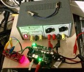
I have a picture of the test setup which I will attach below. I have an old, low cost test power supply I use sometimes. It has been slightly modified from stock. All the rectifiers were replaced with hexfreds, but any ultra-soft recovery types should work as well. The positive adjustable regulator used to be an LM317, but it was replaced at some point with an LT1086. The negative regulator is still an LM337. The fixed +5v regulator is a 7805.
I was trying to test the latest Katana 1.2 with 'thd' output board and isolator board installed. Hooked up the power supply and it still sounded kind of grainy, so I tried a trick that I found worked before for dac output stages which was to connect about 110uf of Wima stacked film caps to each of the +-15v rails. The caps are 10uf, 22uf, and 33uf all soldered and taped together, which is the rectangular red thing in left front side of the picture. That did the trick and the grainynes went away. Katana then sounded really good, best I have ever hear from it and pretty much as good as any ES9038Q2M I have heard. In case you don't know, I have been working on modding another ES9038Q2M dac for the past several months over in another thread, so I have been getting pretty good at knowing how to make them sound their best.
The adjustable supply is available as a kit online for as low as about $70, but the mods I did to it would increase the cost. Don't know how much they actually help either, but they are probably sensible types of things to do.
Lastly, the lower part of the isolator and the RPi were powered with an IFI +5v supply. The three linear supply outputs were used only for Katana.
EDIT: While I am at it might be a good idea to mention something I have been thinking about lately. There seems to be an over-emphasis in the minds of a lot of people on power supply noise specs. Low noise is a good thing, of course, but not the only thing. Some people have reported disappointment with the sound of dacs powered by LT3045/LT3042. There are other types of supplies that have been known in audio for a long time that are known to sound good with some kinds of circuits, the Jung Super Regulator being a good example. One of the things about them is they have very low output impedance across the entire audio band. What I believe the stacked film caps do to help output stages like in Katana is to provide a more low impedance source of quick power at higher audio frequencies. I haven't proved one way or the other whether my suspicion is right on that, but they still work for whatever reason.
In addition, I don't want to talk out of school, but I think Allo took note of my findings with this test power supply and film caps, and they are aware of my thinking on the matter. I think they are persuaded that there is more than low-noise that is at issue to get best sound quality.
Attachments

Last edited:
EDIT: While I am at it might be a good idea to mention something I have been thinking about lately. There seems to be an over-emphasis in the minds of a lot of people on power supply noise specs. Low noise is a good thing, of course, but not the only thing. Some people have reported disappointment with the sound of dacs powered by LT3045/LT3042. There are other types of supplies that have been known in audio for a long time that are known to sound good with some kinds of circuits, the Jung Super Regulator being a good example. One of the things about them is they have very low output impedance across the entire audio band. What I believe the stacked film caps do to help output stages like in Katana is to provide a more low impedance source of quick power at higher audio frequencies. I haven't proved one way or the other whether my suspicion is right on that, but they still work for whatever reason.
In addition, I don't want to talk out of school, but I think Allo took note of my findings with this test power supply and film caps, and they are aware of my thinking on the matter. I think they are persuaded that there is more than low-noise that is at issue to get best sound quality.
I don't have a Katana (yet), but I have a Boss. I'm powering this one with a very simple Choke + zener + cap shunt (so instead of a shunting resistor I use a Hammond 158SA). This is very cheap and works perfectly. It is most likely noisy as hell (zeners are noisy), but it sounds nice.
I have never understood why Allo is focusing on LDO's. If you need to go from 5v to 3.3 you have to. But otherwise you are only asking for problems (oscillation for instance). Also I don't get it why Allo is using a DC-DC converter for the opamp part. Why not skip it and provide a simple dual 15V PSU.
I’ve been following this thread with immense interest, as I’ve been experimenting with an Allo Digione Signature, where I found battery supplies into Supercaps (and sometimes New Class D super-regs) gave best results.
I recently also acquired a Katana, and have applied the same kind of thinking to this, with (so far) similar results. ��
I read earlier that it’s powering the Sparkos board separately where the biggest single gain seems to be made, and I’d definitely agree. ���� This is where, for me, performers acquire real body and physical energy, the timing really locks in (I’m fundamentally a PRaT fan), and the transitions from one part of a song another seem more than just an edit and become a meaningful part of the progression of the song.
For my musical preferences, and in my system with my power supply, this turns the Katana from very good to great. If you’ve not tried it I would definitely recommend it. ��
I am very interested in this. Would you please post some details.... so I tried a trick that I found worked before for dac output stages which was to connect about 110uf of Wima stacked film caps to each of the +-15v rails. The caps are 10uf, 22uf, and 33uf all soldered and taped together, which is the rectangular red thing in left front side of the picture. That did the trick and the grainynes went away. Katana then sounded really good, best I have ever hear from it...
The image is too low res to make any sense from, and it looks like it has 4 caps, not the 3 you mention.
How exactly are these caps wired?
Even a crude wiring diagram scribbled on some paper would help tremendously.
If I am interpreting things right (of which I am doubtful), you have made a filter circuit. What type of circuit depends on the wiring. For example, parallel caps of different values can be used as a low pass filter, and each capacitor will be most effective at a different frequency range based on the capacitor value (and the rest of the circuit including the load).
This is part of what I was trying to get at in my earlier post about trading resolution for precision. In my field (molecular biology), this is something we are constantly battling. The prosaic phrase is "not being able to see the forest for the trees." In other words, when you can focus well on just a leaf (precision) you totally lose the image of the forest (resolution), and you no longer have a reference for what you are seeing.EDIT: While I am at it might be a good idea to mention something I have been thinking about lately. There seems to be an over-emphasis in the minds of a lot of people on power supply noise specs. Low noise is a good thing, of course, but not the only thing. Some people have reported disappointment with the sound of dacs powered by LT3045/LT3042. There are other types of supplies that have been known in audio for a long time that are known to sound good with some kinds of circuits, the Jung Super Regulator being a good example. One of the things about them is they have very low output impedance across the entire audio band. What I believe the stacked film caps do to help output stages like in Katana is to provide a more low impedance source of quick power at higher audio frequencies. I haven't proved one way or the other whether my suspicion is right on that, but they still work for whatever reason.
A focus on precision, will lead to a loss is resolution. This will be true in biology, physics, and audio. The concept is not philosophical, but very real and a constant issue in all the physical sciences. We have all experienced it at one time of another, usually from listening to a system with a vanishing low THD that sounds lifeless.
I find this very interesting as well. Would you be willing to provide some more detail?I’ve been following this thread with immense interest, as I’ve been experimenting with an Allo Digione Signature, where I found battery supplies into Supercaps (and sometimes New Class D super-regs) gave best results.
I recently also acquired a Katana, and have applied the same kind of thinking to this, with (so far) similar results. ��
I read earlier that it’s powering the Sparkos board separately where the biggest single gain seems to be made, and I’d definitely agree. ���� This is where, for me, performers acquire real body and physical energy, the timing really locks in (I’m fundamentally a PRaT fan), and the transitions from one part of a song another seem more than just an edit and become a meaningful part of the progression of the song.
For my musical preferences, and in my system with my power supply, this turns the Katana from very good to great. If you’ve not tried it I would definitely recommend it. ��
I also have a DigiOne and it is a wonderful device.
I really like the idea of a battery in this context. My experience with batteries in other contexts probably mirrors most peoples - not so good, especially in power amps.
The Katana stack though is all very low power stuff, capacitors really should be able to handle transient demands - I like the idea of a super cap.
For some reason, I am just not able to get into buying a ready made supply for each board especially if it means I am going to Frankenstein them into shape. Has anyone used any of the popular circuits that some of the DIYAdio folks have designed? I am starting to lean toward the Super Regulator and a couple of the Hammond 229 series transformers
229D10 Hammond Manufacturing | Mouser
I am very interested in this. Would you please post some details.
The image is too low res to make any sense from, and it looks like it has 4 caps, not the 3 you mention.
How exactly are these caps wired?
I said there are three linear power supplies, not three caps. The +-15v linear supplies have film caps. The +5v linear supply does not.
The four caps you see on top of the other caps are 10uf each. Underneath the 10uf caps are some 33uf and 22uf caps sitting upside down with pins pointing up. The caps are soldered together in two parallel banks with an equal number of caps in each bank. IIRC, there is a total of 109uf in each bank. The caps are connected between each rail and ground. Bottom line: each of the +-15v rails has 109uf of film caps to ground.
Thank you for the fast reply.
I ask my questions only because things are not always clear in words. For example, there is no way to achieve 109uF total capacitance based on a combination of 10uF, 22uF, and 33uf if all three sizes must be used.
I am not being critical in any way, nor am I even trying to point out any real error on your part. I am just trying to understand the circuit, and I must be mis-understanding something if the circuit does indeed have 109uF total.
Would the attached image be a reasonable schematic of your circuit?
This will form a low pass filter with each cap being most efficient at a given frequency. It will take someone with more knowledge than me to figure out what frequencies are actually being filtered.
Here is the manual that contains the schematic for the Elenco XP-720 that is pictured
https://www.elenco.com/wp-content/uploads/2017/10/XP-720K_REV-J-2.pdf
My (meager) understanding is that R2 (150 Ohm) is the part of the PS to use, and this would give us filtering between 32Hz and 106Hz. I often get this sort of thing wrong though.
Either way, my point is that Markw4 was able to get his best results from his set up, and we should try to understand why. The XP-720 uses an LM317T with a simple voltage divider as a regulator circuit, and the humble 1N4001 for rectifiers.
This regulator makes no claims at all to being low noise, but it has a far higher amp rating than everything else discussed.
Marks $10.00 in parts (before his modifications) seems to outperform all the other (and likely expensive) options he has tried.
Poll any group of audiophiles and you will be told that this PS is a waste time, and only suitable for a Tandy 8 track player.
So, are we trying to get the best out of our Katana, or are we trying to spend the most money on it?
So, with all that said, I am very very interested in marks PS, and what has been done to it.
Attachments
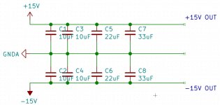
there is no way to achieve 109uF total capacitance based on a combination of 10uF, 22uF, and 33uf if all three sizes must be used.
Good catch. Correct total is 108uf: 33+33+22+10+10. Not that it matters with physical capacitors in this application. Chances are good they measure something other than 108uf, so 109uf might turn out to be more correct in reality. Nonetheless, they are soldered in parallel and the exact value is unlikely to be critical.
Your schematic is the correct basic idea. Just some caps in parallel on each rail to ground.
However, if you read what I wrote originally, there is no LM317 in that supply anymore. Rectifier diodes are different from stock too (and hexfreds are not so cheap). I also said that I don't know how much difference the modifications might make in this application with Katana.
Last edited:
joshua43214,
"each of the +-15v rails has 109uF of film caps to ground"
This means 109uF from +15v to ground "and" 109uF from ground to -15v, for example, your schematic has 75uF total (10+10+22+33) from +15v to ground and another 75uF total (10+10+22+33) from ground to -15v. With film caps your ok because they're generally not polarized, but with electrolytics, watch the polarity as they typically are.
Your sense or understanding of a "low pass" filter is pretty whacked. Sorry, just trying to help you understand...
Here's part of what is likely confusing you. Basically, from an "ideal" capacitor perspective, the capacitors in parallel simply add together. In other words, there's theoretically no difference between an ideal 75uF capacitor and a combination of ideal capacitors comprised of a first 10uF capacitor, a second 10uF capacitor, a 22uF capacitor, and a 33uF capacitor connected in parallel, for example.
However, pragmatically speaking, capacitor "packaging," e.g., the leads, the terminals, the container, etc., makes them less than ideal. In other words, a some frequency a capacitor begins to becomes inductive as well. The bigger the cap, physically and/or electrically, generally the lower the frequency at which this occurs. This goes to the ESR/ESL spec you see in cap data sheets. The "ratio" of the capacitance and the parasitic inductance, along with the ESR is described as the Q - a quantity without dimension. A cap that is hi Q will transition from capacitive to inductive very quickly or over a narrow frequency bandwidth, whereas a low Q cap will do so more gradually over a wider bandwidth. Obviously, the type of material used to make the cap matters too.
Such is a day in the life of a cap designer in making choices and design compromises.
So, in light of the forgoing understanding, what is often done is to parallel a number of capacitors of different values, taking advantage of the relative Qs and ESR/ESL. This is typically done in a decade format, e.g., 0.01, 0.1, 1.0, 10, 100, etc. in uF. This goes to pragmatically providing an "ideal" capacitor...
Some think this sounds good, others, not so much...
I think that is where your understanding comes from....?
The values the Markw4 chose doesn't go to that - the caps generally have the same order of magnitude... However, he chose "film" caps....
Looking at the schematic of the power supply....oh brother,....just no.
That resistor and the pot that it is connected to form a voltage divider that presents a selected voltage to the Vref pin of the regulator that in turn determines the output voltage.
With a regulator, you need to look at the data sheet and see what the output impedance is relative to frequency for the regulator. This is much, much less that that voltage divider.
Yea, that's just wrong...:>)
The thing that is really "bad" about the LM317, the T is a somewhat improved version, is that it doesn't really present a low impedance above about 1 kHz and you need to rely on caps for that function...which then goes to regulation and stability, etc. and pretty soon, you find yourself looking for a better reg, particularly with digital circuitry....
So, that's more where Markw$ is coming from.....
That help with your understanding???
Catching up #1...
Sorry for the slow responses, been busy doing other stuffs! I'll try to get caught up on responses in the next day or so, beginning here.
@Jonathan P, you are very welcome. BUT it is everyone's contributions here that make this thread useful for all.
On jumper settings with the Isolator 1.2, the best document for that is the Katana Default Setting document. You can get it from the Allo website under the Katana page's Support & Downloads section. I've been working up a summary of the Katana that describes the components and various power combos. Your question had me realize I need to add settings for each combo. I'll get that out soon.
AND as @jrocker said, with an Isolator 1.2 you need to have the jumper on J30 on the DAC board to make sure power gets to the Isolator 1.2 output side. EVEN though there is a USB-C on the Isolator board, that is only for feeding power to the input side and RPi IF the Isolator 1.2's J26 jumper is on.
@chris14, thanks for the reminder on Allo's promised linear PSU. Hopefully cdsgames will see this and provide an update. AND I bet you are right in that for most, it will be a good single-box solution.
@Markw4, thanks for posting your power setup here and including the details that before were only on the ES9038Q2M board thread. That will be very helpful for all. One question, have you tried a 2nd 5V supply to the Katana for powering the Microprocessor board separately from the DAC board? See the report from that 'audio friend' of mine above in post #137... he found that not only to be a good upgrade, but he found the regulator quality made a noticable and significant difference there. Since that report, I've also tried a slightly better regulator board on the 5V to the Microprocessor board in my Katana setup and also heard an improvement, though I don't believe the difference between the two regulator boards I used were as large at the ones my 'audio friend' used. Based on his report and my confirmation, I bet you still have some performance you can wring out of your setup! Or have you tried a separate 5V supply for the Microprocessor board already?
& I need to say I think your small cap banks are very good ideas and worth duplicating.
Also, I found your comments about the reconstruction filter interesting... which one produced the 'slightly thick or muddy' sound and which did you settle on? I'm still using the minimum phase slow roll-off filter, but I chose that early in the Katana development cycle and really need to go back through them again and see if that is still my choice. I did find small differences between them all... but at that time the minimum-slow filter brought out the best in the unit. SOOOOO many porcupines, so little time!
@joshua43214, @Markw4, and @jrocker, thanks for your clarifications on the LT3042/3045 w/pass transistor boards. In addition to the one that Markw4 linked, this is the one my 'audio friend' uses:
0.8uV Ultralow noise DAC power supply regulator 3.3/5/7V 1.5A*x2 - DIYINHK
Personally, I have not used any of these yet. I have more experience with the multiple-paralleled LT3042/LT3045 regulator boards such as those sold for a time by former DIYAudio poster OPC, by current DIYAudio poster Stammheim at mpaudio.com, and what I believe are similar ones here:
0.8uV Ultralow noise DAC power supply regulator 3.3/5/7V 1.5A*x2 - DIYINHK
I've used a number of the OPC and the MPAudio boards and must admit I prefer the latter. It is not a huge difference, but worthwhile... a bit more detail, sonics get a bit more 'see-through'.
I really need to get a couple of the pass-transistor versions to try. I suspect there might be some applications where they'd work and sound better.
& @joshua43214, in my experience, I prefer and use CMC's on supplies where I am driving what I call 'deep digital' circuits, such as computers (like the RPi) or networking gear, as much to reduce the amount of noise they generate from getting back into my AC lines. OTOH, I on 'mixed digital/analog' and all analog circuits, I prefer them without those chokes, though I typically use a C filter across the hot and neutral on their supplies.
@joshua43214 thanks for the question on the power needs of a 'class-A' circuit... & @abraxalito for your great explanation of what is so with them. On the question of how much the quality of the power to the opamp board matters to the overall sonics, honestly, I don't know and haven't seen any reports of experimentation along these lines EXCEPT for those who have reported (along with Allo) that providing separate +-15V is a very good upgrade. I suspect it does matter a lot and have plans to try some lesser regulator setups than the close-mounted Sparkos regulators I use now but that's a ways off.
@joshua43214 you may have seen my report on Ultracap supplies in post #126 above along with some musings on the limitations of battery (specifically the currently popular LiFePO4 cell-based ones) and Ultracap supplies with the Katana, due to those who have used them reporting the best results where they directly feed the circuits without any intervening regulators AND the difficulty of doing that with the Katana. BUT based on my experiences as reported in post #126, I'd say they'd be a good
Katana source if implemented well.
@Jonathan P, that DACT supply looks interesting. BUT I have not seen any reviews or comments about it and my cursory search didn't turn up any. AND it is pricey. Also, they provide very little info on the circuit details... something I'd want to see before I plunked down my coins on a unit without a lot of press.
IF you want to get a good, well reviewed ready-to-use power supply for 5V look at the SBooster line. I've seen a number of people commenting very positively on them. BUT still, pretty pricey. AND they don't have a ready-to-use +-15V option that I see.
The EBay / DIYINHK options you listed are those that others have tried and gotten good results from for the 5V, used within their current limitations.
On +-15V supplies, the ones @wushuliu listed should be very good. I use a number of LDOVR's other products and am VERY happy with them. Another option are the ones from MPAudio.com where a board with dual +15V outputs can be configured as a +-15V supply. I also have the intention of trying one of these soon as an alternative +-15V supply.
@Ralph G, I know Allo has gotten very good results from their LDO's in the past. Even their initial offering, the Piano DAC series, used LT3042 regulators and they still hold up well against other PCM51x2-based RPi DACs. AND early in the Katana development Allo stated they were incorporating the DC-DC converters to make it easy to power the stack with 1 or more 5V supplies, something that has seemed important to some. OTOH, one breakthrough RPi DAC for me was the Dial AUdio one that requires a +-15V supply. With a good supply (the +-15V output of a Silent Switcher did not qualify as that for me on this DAC), it was a significant step above all of the then-other RPi DACs that used DAC chips with integrated output stages in dynamics, clarity, and overall lifelike presentation. While something like the Katana is another significant step above it, it of course comes at a significant cost differential too. AND back to your comments on your choke-zener-cap shunt, I can get how that could be a good sounding option. Love to get a schematic, if you don't mind... please send a PM. AND back to the Dial DAC... the +-15V shunt regulators I used that worked well also used zener diodes to set the voltage. Sorry, it is a friend's proprietary design and I can't share it, but think of it as a less-complex Salas-styled regulator (also likely not as good as a Salas too). So I know they can be 'good' sounding, if used correctly.
@RX8R3ROD, thanks for your report. Sounds like you're hearing what many others of us are reporting... that the Katana powered well can be a very good DAC. Love to hear more details (and see pix) about your setup. Others are interested in battery supplies.
I'm gonna stop here before this post gets too long to submit. I'll respond more later this week... also, I have a further report from my 'audio friend'... and I still have to post more info on my modified Jameco linear regulated adapters, as previously promised.
Hoping all had fine Holidays, whatever you celebrate!
Greg in Mississippi
P.S. I should also remind that a few weeks back I updated the first post in this thread with info on some of the power options discussed. I will do that again soon with some of the recent additions.
P.P.S. @joshua43214, batteries can be used successfully in amplifiers, though they take some heroic efforts. See these 2 threads:
It didn't explode....... YET (aka niges amp) - Tir Na HiFi
and
Go BIG or go HOME... Class A amplification done Lifepo4 style - Tir Na HiFi
Last edited:
joshua43214,
Your sense or understanding of a "low pass" filter is pretty whacked. Sorry, just trying to help you understand...
I do really appreciate you taking the time to write a long reply, and I do read your comments with interest. However, I do not appreciate your tone.
Total capacitance does add together, there is no confusion over this.Here's part of what is likely confusing you. Basically, from an "ideal" capacitor perspective, the capacitors in parallel simply add together. In other words, there's theoretically no difference between an ideal 75uF capacitor and a combination of ideal capacitors comprised of a first 10uF capacitor, a second 10uF capacitor, a 22uF capacitor, and a 33uF capacitor connected in parallel, for example.
However, pragmatically speaking, capacitor "packaging," e.g., the leads, the terminals, the container, etc., makes them less than ideal. In other words, a some frequency a capacitor begins to becomes inductive as well. The bigger the cap, physically and/or electrically, generally the lower the frequency at which this occurs. This goes to the ESR/ESL spec you see in cap data sheets. The "ratio" of the capacitance and the parasitic inductance, along with the ESR is described as the Q - a quantity without dimension. A cap that is hi Q will transition from capacitive to inductive very quickly or over a narrow frequency bandwidth, whereas a low Q cap will do so more gradually over a wider bandwidth. Obviously, the type of material used to make the cap matters too.
...
That help with your understanding???
ESR/ESL has the units Ohms/Henrys, this is not a unitless number.
I think you mean that Q = Xc/ESR which is a dimensionless number. It is a rating of the "quality" of a capacitor for a given capacitance and frequency.
Xc = 1/(2pi*c*f) = Capacitive reactance. It is a measure of the impedance of the capacitor, its units are Ohms, and it is dependent on capacitance and frequency. It is calculated for each individual capacitor. It should be clear that as frequency increases, impedance decreases.
Xc is perhaps the single most important aspect of a capacitor, and it defines when a cap stops behaving like a capacitor, and starts acting like a conductor.
For ESL, Z = 2pi*f*L, where Z is impedance and is measured in Ohms, and L is parasitic inductance.
When Z = Xc the impedance of the cap is at its minimum and the capacitor is self resonant.
Note the 2.2uF cap in the attached image. Note there is no resistor on the rail to "complete" the RC circuit. This cap filters high frequency noise - it is a low pass filter. What remains is low frequency (Hz ~= 0) DC current.
Packaging and all that is pretty important, but it is meaningless unless put in the context of the fundamental characteristics of a capacitor. In other words it is a cap before it is a film/ceramic/electrolite/etc cap.
Hopefully this will clear up some confusion.
Attachments
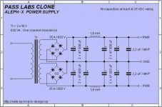
Note there is no resistor on the rail to "complete" the RC circuit.
However, there is an inductor to make an LC circuit. 🙂
Hello joshua43214,
It might help to better understand how to best communicate with you if you would be willing to say a little about your background in relation to electronics. Obviously, you understand mathematics and physics to some extent or other, and you seem to like to understand things in terms of mathematical models. However, you also seem somewhat new to electrical engineering concepts and circuit analysis. Would that be an approximately correct understanding on my part?
Regards,
Mark
- Home
- Source & Line
- PC Based
- Getting the best out of Allo.com's new Katana DAC...