That’s why I was shocked with not all 431 regulators would work here. Did not think 1mA is not “good enough”.
If your jfets don't draw more than say 7mA you're probably ok to use the regular TL431 but then you also have to take into consideration the temperature coefficient of the jfets which will tend to draw more current as they get hotter etc.
So it could be a borderline situation using TL431 depending on the jfets you have.
Another option is use a transformer with 20V secondaries.
That will bring some added benefits too.
So that's quite a few cat skins right there.
You can't say I don't help you bloody bastards.
Hahahaha
So it could be a borderline situation using TL431 depending on the jfets you have.
Another option is use a transformer with 20V secondaries.
That will bring some added benefits too.
So that's quite a few cat skins right there.
You can't say I don't help you bloody bastards.
Hahahaha
Last edited:
Cat skin no. 1 ensure Jfets do not draw more than 6 mA at operating temps in the circuit
Cat skin no. 2 use programmable shunt references with lower current requirements - linked earlier
Cat skin no. 3 employ resistor mod - shown earlier
Cat skin no. 4 use transformer with 20V secondaries
Cat skin no. 5 employ 2 or more of cat skins 1 through 4, eg 2 + 4 etc
Cat skin no. 42 Vegemite on toast.
Last edited:
If your jfets don't draw more than say 7mA you're probably ok to use the regular TL431 but then you also have to take into consideration the temperature coefficient of the jfets which will tend to draw more current as they get hotter etc.
So it could be a borderline situation using TL431 depending on the jfets you have.
Even 7mA could cause issues, let's say 6mA.
Cat skins 2 through 5 is going to be the best solution here.
Last edited:
Thanks Pico for the many options. It looks like the least amount of surgery is replacing the TL431 itself. We really ought to be more specific in the diyaudio store BOM. Also, would I be able to get biasing and everything else working with the wrong part? I'm trying to read up on this and the other F4 thread on TL431--it has caused quite a bit of pain.
Yesterday morning I rebiased the amp. Starting cold at 130 mV and then biasing to 220 mV after an hour. I don't know if it was this or the fact that it had now run for a good 20 hours, but it has totally changed character. The bass boost I had alluded earlier is gone. It is now silky smooth and the imaging is fantastic. I can listen to this amp now. There is still something that is annoying me but I can't quite put my finger on it. The M2 makes me feel relaxed where this one doesn't. Maybe the RME isn't as comfortable swinging so many volts.
Hate to make a Mouser order for one part.
Thanks Pico for the many options. It looks like the least amount of surgery is replacing the TL431 itself. We really ought to be more specific in the diyaudio store BOM.
This was kind of a new discovery while pondering potential problems with this circuit.
Not sure anyone else had picked up on it before, maybe because others hadn't had problems before or they just hadn't noticed it.
There is still something that is annoying me but I can't quite put my finger on it. The M2 makes me feel relaxed where this one doesn't. Maybe the RME isn't as comfortable swinging so many volts.
Hate to make a Mouser order for one part.
Fix the shunt reference issue, that will further improve things, quite a bit.
Think of something else to buy.
Also, would I be able to get biasing and everything else working with the wrong part? .
Bloody oath. Essentially what you have is a biased amp through a resistive voltage divider circuit.
The shunt reference is doing absolutely nothing in your circuit.
This is like mixing vegemite with peanut butter. That's a bloody jailable offence right there.
Last edited:
Yeah. You should measure 2.5V
You have a problem with your shunt. You need more current. This should further improve things quite a bit.
TLVH431 will operate with 100uA. You could try that. There are some other that operate with lower current.
This discussion cued me to open up my amp and do some measurements. I've got 2.23v across r9 and 12.67 across r7. This looks to be right on the edge of ok. Should I be concerned?
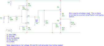
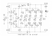
Here is a schematic of the input buffer, voltage amplification section, and
the following buffer. This is from my memory and notes I have here at
work, but I think it is correct.
Whoops. I had J2 upside down. This is corrected (ie: the sources of
J1 and J2 should be toward the POT).
Attachments
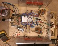
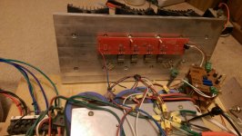
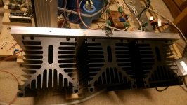
Some pictures would also be nice. I'd love to see an example of an f4 with pTp wiring. I think these are my final amps, so I like to entertain any option that people argue increases perceived sound quality.
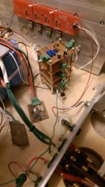
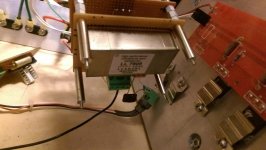
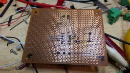
Here are some pics. The stack is the LL7905 transformer, the input buffer, the second buffer (the one after the transformer), and the biasing section of the OPS. The picture shows an LSK389 input section. It is not the input section I am currently using (which is shown in the schematic), but it does show the PtP wiring. The other boards in the stack are of similar component count and complexity.
Attachments

This discussion cued me to open up my amp and do some measurements. I've got 2.23v across r9 and 12.67 across r7. This looks to be right on the edge of ok. Should I be concerned?
I would measure voltage drop across 10k resistors, R7/R8.
If it's less than 12V then yes. You should fix it.
Last edited:
R6 and R7
I need to get in there and check mine also. Sound was fantastic from the start but my OCD will bother me until I know where mine's running.
I need to get in there and check mine also. Sound was fantastic from the start but my OCD will bother me until I know where mine's running.
Ordered one of your recommendations.
I read through this thread and some of Jacco's comments on the TL431. I still don't think I understand how it operates. If the Vref is at 2.5 V, then Vout, or the voltage between the gates should be 2.5 x (1 + R8/(R9 + P1)), which is between 7 V and 9 V approximately. How do you calculate the current flowing through the device, I-ka? Is it simply the current flowing through the R6? In my case, that would be 9.6 V / 10k = 0.96 ma, less than what is needed to operate the part. Is that right?
Found one of Papa's comments that the TL431, presumably the part he used, needs at least 300 uA for proper operation. So, any version needing I-ka min below that value should do the trick.
BTW, since yesterday, after the rebiasing and relocation of bridges, the amp is dead quiet, even with my ear on the 110 db/W horns. But I am going to use a riser panel, tilt the trafo and put one of those Antek cans on it, if they will fit. That should give more room in the chassis center to put the bridges.
First measure voltage drop across 10k resistor R6 or R7.
This will tell you total current eg 12V/10k = 1.2mA
Now determine current in programming resistors = 2.5/(P1+R9)
Let's assume P1 + R9 = 10k
So current would 2.5/10k = 0.25mA
So cathode current would be 1.2 - 0.25 = 0.95mA
That would be bad.
So simplifying things, you want to have a 13V drop across the 10k resistors if using TL431.
Or use those devices linked earlier. They require no more than 100uA, to operate correctly.
Attachments
Last edited:
I'm pretty sure I-ka equals the current through R6 minus the current through R9.
Correct
BTW, since yesterday, after the rebiasing and relocation of bridges, the amp is dead quiet, even with my ear on the 110 db/W horns. But I am going to use a riser panel, tilt the trafo and put one of those Antek cans on it, if they will fit. That should give more room in the chassis center to put the bridges.
It's going to keep getting better once you've made all the changes
- Home
- Amplifiers
- Pass Labs
- F4 power amplifier