Thanks a lot Mr Pass. You're an asset to the DIY and Hifi community for making such interesting products and then allowing us to try them out for ourselves!
Any ETA on the full service manual? I cant wait to get to work on it, but I'd like to do as much reading as possible first because i'm a noob")
Thanks again!
Any ETA on the full service manual? I cant wait to get to work on it, but I'd like to do as much reading as possible first because i'm a noob
Thanks again!
Fig. 2 in the Zen V2 .pdf must do the trick nicely IMO.
According to the paper, the current source
"can be further developed into a current variable current source as seen in the Pass Labs Aleph amplifiers."
and: "it uses the same device as the gain transistor, both being the cheaper and more easily obtained N channel types."
So, I presume the F2 can also be further developed with an Aleph current source which will benefit the efficiency of the amplifier.
/Hugo
You use an Aleph current source in a current source amp, but
it gets trickier. Feedback around the gain stage ensures
stability of the system, but when you run something like an
F2 with no feedback, you take a second look at stability when
applying AC gain in the current source.
it gets trickier. Feedback around the gain stage ensures
stability of the system, but when you run something like an
F2 with no feedback, you take a second look at stability when
applying AC gain in the current source.
Netlist said:Fig. 2 in the Zen V2 .pdf must do the trick nicely IMO.
According to the paper, the current source
"can be further developed into a current variable current source as seen in the Pass Labs Aleph amplifiers."
and: "it uses the same device as the gain transistor, both being the cheaper and more easily obtained N channel types."
So, I presume the F2 can also be further developed with an Aleph current source which will benefit the efficiency of the amplifier.
/Hugo
for me ,second important characteristic of Papa's messing with DIY crowd is his Lego approach ; he succeed in teaching us how to understand each Lego particle,and how to mix them in making something new ; at least new to inventor of sayed moment
first important characteristic is ,without doubt, his humorous way of thinking and presenting

Talking about Lego. Its quite funny to take the Lego approach.
Since many of the building blocks are used in several amps, its easy to plug these "Lego"-blocks together. Make yourself a little collection of CCS's and Reg's and you are ready to play
Steen
Since many of the building blocks are used in several amps, its easy to plug these "Lego"-blocks together. Make yourself a little collection of CCS's and Reg's and you are ready to play
Steen
Attachments
Steen and to all our buddies,
I got a nice ball going back through the older threads where we “back engineered” the F2 with all those tips we got from our friend Nelson.
Just for the record on how close we got on doing our task. Of course we new before hand that there was no active voltage regulator on the original but any way we decided to add one a la ZV4.
Now the original has a different schema for biasing Q1 and has a slightly higher feed back (?), 100K against 440K resistor if memory serves me well.
The back engineered one has a more elaborated CCS (couple of extra caps) similar to other later Zen’s which may or may not make much difference.
Also Nelson set the source resistor for Q1 to 0R66 against 1 Ohm which may change somewhat the whole bias of the Amp to my understanding.
I do have the stuffed boards for the amp that Steen, kindly enough, sent me but up to this date I have not used them (shame on me) because time has not been on my side. Now that the original schematic is out, thanks Nelson, is very tempting to make those small changes and enjoy the F2 clone, hope this day is close enough… Xmas is coming soon!!!
Re: F2 Clone Delight
Scott,
hehehe we all take the risk, is part of DIY enjoyment I'm sure also that Nelson has experianced this at some point in his life...
We did developed a set of boards for the "Back Engineered" version and a set was etched by Steen, he also tested them for a while some time ago. the art work is available for you to use or anybody else for that matter but will not conform to the schema shown by Nelson.
As far as I know no one has make a small lot of boards for this amp or the BE one, except of course First Watt.
It realy calls my atention that someone will use this amp for a subwoffer, it only has 5 watts, good enough for an efficient fullrange though.
Scott Valley said:something that won't turn into molten aluminum when switched on.
Scott,
hehehe we all take the risk, is part of DIY enjoyment I'm sure also that Nelson has experianced this at some point in his life...
We did developed a set of boards for the "Back Engineered" version and a set was etched by Steen, he also tested them for a while some time ago. the art work is available for you to use or anybody else for that matter but will not conform to the schema shown by Nelson.
As far as I know no one has make a small lot of boards for this amp or the BE one, except of course First Watt.
It realy calls my atention that someone will use this amp for a subwoffer, it only has 5 watts, good enough for an efficient fullrange though.
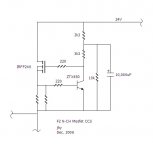
Babowana said:F2 N-ch MOSFET CCS
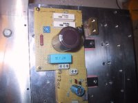
This way?
I just replaced "all" 2k2 with 3k3.
And, thought of 10,000uF on hand.
Papa, don't hate me . . .
looks good enough
Trimpot P1 on Mr. Pass's schematic is connected different from what we did. It has the viper connected to the gate of Q1. We had it connected to Gnd as far as I recall. Maybe that was the cause of the problems there was adjusting the F2 clone?Now the original has a different schema for biasing Q1 and has a slightly higher feed back (?), 100K against 440K resistor if memory serves me well.
I had no turnon thump worth mentioning when I turned on the F2 clone. Maybe the regulator had something to do with that?
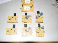
Could be fun making a few perfboards with the correct schematic, the F2 CCS's I posted on the picture earlier, just needs one cap changed to 15.000uF. Wouldnt 10.000uF be enough? I cant figure out how to calculate the timeconstant or whatever it is that determins the size of C4.
It beats me how people can consider a 5 watter for a subwoofer
For reference I have attached the clone schematic.
Steen
Attachments
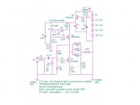
steenoe said:Trimpot P1 on Mr. Pass's schematic is connected different from what we did. It has the viper connected to the gate of Q1. We had it connected to Gnd as far as I recall. Maybe that was the cause of the problems there was adjusting the F2 clone?
Both are voltage dividers for biasing Q1, Nelson's schem seems easier to set though, what did call my attention is that he uses only 100K + some that acts as a bit more feedback in my book against our 440K. As far as I know the way you connect the pot is not important but Nelson wisely enough connected the wiper to the leg that will carry the least current and uses two more resistors in an elegant way. In this setup is easier to vary the FB chaniging only R6.
Very nice Nelson
Have to say I'm surprised at the folks who are surprised at the use of the F2 to drive a woofer. It is perfectly well suited, which is exactly why Dick Olsher pounced upon it for his Basszilla--and why I'm keen to build this speaker. After all, the idea behind "First Watt" is to make the best possible use of the all-important...first watt.
The concept and application(s) of the F1, F2 and F3 are thoroughly explored on the Six Moons web site (www.sixmoons.com) in an extensive series of First Watt product reviews which can be found in the site's audio archives. One of these is specifically devoted to an explanation of the concept and advantages of the current source amplifier, with commentary from Mr. Pass.
Thanks to those who have offered encouragement in my pursuit of an F2 clone. A pursuit not yet realized, but the day she is young and I am hopeful good things will happen in the weeks and months ahead...
I have a bit of a newbie question but I'd really appreciate it if anyone could help me out here. I'm a bit of a noob when it comes to this stuff, but everyone has to start somewhere. I'm really keen to build a F2 to go along with my newly constructed Dallas horns.
1) What voltage ratings do I need to buy for the various components on the circuit that nelson kindly posted. I'm really keen to purchase all the stuff I need to get started ASAP, but I dont want to waste money buying high voltage caps when not needed.. and i definitely dont want to fry any parts. If anyone could post a list of part numbers (eg C1, C2, R1 etc) and their voltages I'd really appreciate it
2) Does the F2 use the same power supply as the F1?
3) Whats the specs on "LED 1"?
4) Whats the specs on "L1"?
Thanks in advance! You will make my day and help bring the joy of audio into someone's life!
hugz said:1) What voltage ratings do I need to buy for the various components on the circuit that nelson kindly posted. I'm really keen to purchase all the stuff I need to get started ASAP, but I dont want to waste money buying high voltage caps when not needed.. and i definitely dont want to fry any parts. If anyone could post a list of part numbers (eg C1, C2, R1 etc) and their voltages I'd really appreciate it
2) Does the F2 use the same power supply as the F1?
3) Whats the specs on "LED 1"?
4) Whats the specs on "L1"?
1) All resistors at 1/4W (0.25W) rating except the resistors marked as 3W on the drawing. As the dc voltage between the power supply line and the ground is 24V, all capacitors rated at min. 24V (35V is common in our market) acceptable
2) Yes, we can use the same as the F1
3) About 3V at 20mA
4) Papa said L1 had no meaning. It just indicates that R23-26 (3W) are wire-wound resistors. So, there is no actual L1
Hope this will help
Hugz
Some answers to your questions,
I would suggest lytic caps to have a rating of 35V or more. Other components like resistor and film caps usually have a much higher rating as a minimum so you don’t have to worry about those.
LED’s for this application (power ON for front panel) are all similar take your pick on color and physical size, usually Pass products and Pass clones uses blue color but that’s up to you.
L1 is a representation of the inductance found on wire wound resistors R23/26 so actually L1 does not exist as a physical component, just forget about it and choose wire wound resistors for R23/26.
This is a very nice and easy project to start with, as simple as the first Zen so go ahead with it and keep us posted about your progress. I’ll be building one F2 clone too
- Home
- Amplifiers
- Pass Labs
- DIY F2 clone