Manu said:
Yes I do it with laserprinter (drekky 600dpi). It works well as long as traces are not too large. Planes for instance don't come out well ... Need 2 surimposed transparencies.
Actually I tried with inkjet photo printer also but didn't get good results (no sharp edges etc... )
But now that you said that ... Seems that I should look for better inkjet Trsprcies ...
I could do it (since I already began I could say continue) ... But I am not LL nor Speedy Gonzalès ...
I would copy all 3 projects boards : Pre, Shunt and reg.
Manu
I only use 1 layer trsprcies. The tracks get pitch black on the sheets I use. It is some HP stuff, that has a coating on the printside, that really takes up the ink well.
Manu, I didnt know you were into board designing. How nice.
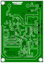
Edit. That board looks great
Did you increase the room for the opamps bypass caps? it could use a mm or two extra space.steenoe said:
It is some HP stuff, that has a coating on the printside, that really takes up the ink well.
Manu, I didnt know you were into board designing. How nice.
I ll give this HP stuff a try ..
Board designing is a big word
.Its just that I think a copycat can learn a lot in this field.
For me its worth the effort and time spend...
I consider the board design to be an essential part of a project.
Manu
Manu said:
I ll give this HP stuff a try ..
Board designing is a big word
Its just that I think a copycat can learn a lot in this field.
For me its worth the effort and time spend...
I consider the board design to be an essential part of a project.
Manu
I just checked the box of transparencies, there is no number, but it says:
"HP premium transparency film" Inkjet 0,13mm thickness.
steenoe said:
Edit. That board looks great
Thanks, but its really just a start ...
The bypass caps are pretty at the same place as on Tonys board.
The only difference is that I just moved the ground trace on the left side a little more to the left ...
Manu
edit :
"HP premium transparency film" Inkjet 0,13mm thickness.
Mine is Staedtler lumocolor 0.10. Its coated and it seems that the coating presents some // lines and not an uniform surface. That could explain the result I was not happy with ...
Manu said:I stared with Shuntreg board copy
Manu said:With The OPA reg also ...
Manu

Gee guys, you are running quite fast while I was sleeping.
Manolo,
Thanks for the offer for doing gerbers, from my point of view there will be several things to consider before tackling this work.
First and most important would be over the shuntreg. I have about three new files for this one on a compact size layout which is less than half the size of the one you have and might be interesting to consider, but of course needs to be tested first before committing to Gerber’s. On this one, Steen suggested having a trimpot for setting the voltage in replacement for R4 and I’m in the process to finish it.
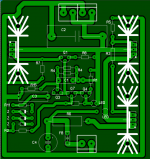
On the NS10 I would suggest eliminating the Input to the left and only deal with “Alt” one.
On both preamp / buffer (NS10 / B1) Steen has eliminate the use of lytic decoupling caps which I found an excellent option when using the shuntreg… so these could be eliminated altogether from the layout but they could be left there as an option also… a matter of taste.
And of course we have the upcoming B3 which we could also include on this project
Manolo,
Thanks for the offer for doing gerbers, from my point of view there will be several things to consider before tackling this work.
First and most important would be over the shuntreg. I have about three new files for this one on a compact size layout which is less than half the size of the one you have and might be interesting to consider, but of course needs to be tested first before committing to Gerber’s. On this one, Steen suggested having a trimpot for setting the voltage in replacement for R4 and I’m in the process to finish it.
On the NS10 I would suggest eliminating the Input to the left and only deal with “Alt” one.
On both preamp / buffer (NS10 / B1) Steen has eliminate the use of lytic decoupling caps which I found an excellent option when using the shuntreg… so these could be eliminated altogether from the layout but they could be left there as an option also… a matter of taste.
And of course we have the upcoming B3 which we could also include on this project
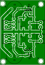
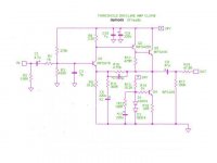
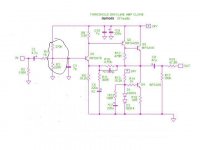
Toole Shuntreg
There is an interesting note here regarding the shunt R9 resistor on which Cetoole commented that when running class A circuits (most all our preamps) is not needed and that actually on his schematic it was there as a load for the Spice simulation.
On the new Compact version I’m finishing I have deleted this resistor so all the shunt current will be managed by Q2 in which case we need to set the CCS accordingly with less source current just not to overload the transistor. All other parts of the circuit remains the same and an etch file will be made available if you whish to test this new configuration as soon as I finish it.
Aye Aye Capitano,
I ll simply implement your mods and suggestions as one goes along
There is no hurry for the gerber.
Looking forward to see your new (Steen already told me that you're working on it) compact version of the shuntreg.
Should look familiar to you
Manolo
I ll simply implement your mods and suggestions as one goes along
There is no hurry for the gerber.
Looking forward to see your new (Steen already told me that you're working on it) compact version of the shuntreg.
apassgear said:Anyway your artwork is
Should look familiar to you
Manolo
Attachments
Mucho rapido Manolo, very nice work, I like it and I’ll be happy to work with you on the mods for the NS10.
I’m quite into the shuntregs mods at this time wanting them to be very useable and compact and I’m sure you could be of help on some issues.
The board size at the moment is around 67x39mm and would like to keep it as close to this as possible, but I’m wondering on C1 and C3 cap size, the layout at this moment calls for a 7.5mm lead space for these but don’t know how popular this size is but know they exist; seems that 10mm spacing is more common on these sizes. On the other hand using 10mm will cause constrain on the layout.
Any input on this issue?
Muuchas Gracias,
at your service Master... its a pleasure to copy your work ...
As for the Cap size ... Even if they re not that exotic, RM 7,65 caps would be a limitation in choice, so allowing for 10mm if possible is a good idea.
I don't know right now which brand/size I woud like to use ... so I think its good to have a margin...
Manu
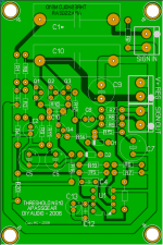


Manu said:
Brd size : 90x60 mm [35.4 x 23.6 inches]
Manu
Seems your calculator is not working

- Status
- This old topic is closed. If you want to reopen this topic, contact a moderator using the "Report Post" button.
- Home
- Amplifiers
- Pass Labs
- Threshold NS10 Lineamp PCB