Redesigned Nch VFET pwr filter board; improved & flexible thump muting; FREE giveaway
It occurred to me that a PCB I've designed for another project, might also work very well for Nchannel VFET amplifier owners. So I've built up and tested a few of these boards, and would like to give them away, absolutely free of charge, to highly motivated Nch VFET owners. To be clear: I'm giving away fully populated, stuffed, soldered, and tested boards. I'm hoping to find one or more recipients, who have all of these properties
I'll collect all PM replies (if any!) and decide who to send the boards to. I'll give people a few days to respond since many folks only look at diyAudio once or twice a week.
WHAT'S DIFFERENT ABOUT THIS PCB
If the board successfully eliminates thumps of real Nch VFET amps, in the field, I'll post the schematic and Gerbers. If it's a failure, not so much.
_
It occurred to me that a PCB I've designed for another project, might also work very well for Nchannel VFET amplifier owners. So I've built up and tested a few of these boards, and would like to give them away, absolutely free of charge, to highly motivated Nch VFET owners. To be clear: I'm giving away fully populated, stuffed, soldered, and tested boards. I'm hoping to find one or more recipients, who have all of these properties
- You built an Nchannel VFET amp yourself
- It has LOUD thumps at turn-on or turn-off or both
- These thumps vex and annoy you
- You are highly motivated to get rid of the thumps
- You are prepared to promise that you'll install the new board right away and listen to it thump (or fail to thump!!) right away
- You and your Nch VFET amplifier are located in the 48 contiguous United States
I'll collect all PM replies (if any!) and decide who to send the boards to. I'll give people a few days to respond since many folks only look at diyAudio once or twice a week.
WHAT'S DIFFERENT ABOUT THIS PCB
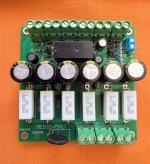
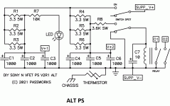
- Inputs and outputs use connectors instead of solder holes; max current rating exceeds 30 amperes per connection
- The board can accept either 12V or 24V relays (coil voltage), giving more options when buying parts during a severe worldwide component shortage
- At switch-off, the loudspeaker outputs are muted immediately with zero delay. Slightly fancy circuitry using zener diodes, empties the relay coil energy very quickly.
- At switch-on, the loudspeaker outputs are un-muted after a user selectable delay. There are five delay selections, guaranteed to be monotonic, but not all that precise, since they depend upon the threshold voltage of a 2N7000 junkbox MOSFET. And 2N7000 threshold voltage is highly variable
- I measured the turnon delay-till-muting-ceases on the first populated board, pictured below; for the five user selectable jumper settings on that board, its measured delay times were:
Quickest: 2 seconds
2nd quickest: 6 sec
3rd quickest: 12 sec
4th quickest: 17 sec
Slowest: 24 sec
- Other boards with other 2N7000s will no doubt vary. And that's why there are five settings; it lets you fiddle around and experimentally find a setting on YOUR board with YOUR 2N7000, that gives a delay which is acceptable to YOU.
If the board successfully eliminates thumps of real Nch VFET amps, in the field, I'll post the schematic and Gerbers. If it's a failure, not so much.
_
Attachments
Last edited:
Insert a 27k dropping resistor at R7 as per @Vunce suggestion.
jeff
Thanks. I went back to review Vunce's notes. I'm not getting any turn on thump but I do get large turn off pop from the speakers.
Very generous of you Mark, if it proves successful with testing by yourself and others, then I look forward to the schematic and gerbers in the future. Good luck with the project. I am sure you will get a few members sign up.
A most excellent offer Mark!
Turn-on pop is not so bad with my N-channel VFET, but turn-off is louder, but not a show stopper. I would be interested in mitigating this at a later date, but it's not a priority right now.
Just curious what others see as the measured turn-on delay with their N-channel PS boards. Mine is a few milliseconds, which seems way to short (almost instantaneous with the flip of the switch). Has anyone played around with different time constants to see the effects on reducing the pop?
Last edited:
Unfortunately I don't meet many of those criteria, but it's nice to know it may be let loose in the wild if it works.
Another thank you Mark!
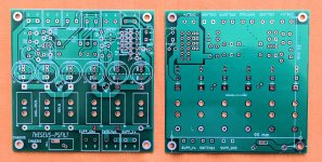
BTW, I really like the silk screen on the bottom of the pcb, where it explicitly marks off 90mm between centers of the mounting holes.
Another thank you Mark!
BTW, I really like the silk screen on the bottom of the pcb, where it explicitly marks off 90mm between centers of the mounting holes.
Can we pretend that my home temporarily is within the 48 states-thing?
(I still wouldn‘t meet the conditions as my build isn’t done yet)
Thank you very much, Mark, for yet another cool contribution! I’m curious to see if I‘d need this 🙂
(I still wouldn‘t meet the conditions as my build isn’t done yet)
Thank you very much, Mark, for yet another cool contribution! I’m curious to see if I‘d need this 🙂
The pops on mine are negligible - although it's only driving the upper frequencies. Music begins at switch-on, but the led turns on later, presumably after the caps on the filter board have charged up.
I'll find out how it behaves with ESLs next week.
I'll find out how it behaves with ESLs next week.
I almost make those criterias: "Howdy partner!  Would you like cheese with that? Who's the vice president?"
But my Pops are for real.
Would you like cheese with that? Who's the vice president?" But my Pops are for real.
Last edited:
i has loud thumps at turn-off (97db Speakers),read that 1000uf between v+ and ground will help. wil this work with the n channel to ?
Andreas
Andreas
Plz explain. 🙂 Visually!
Or did you just get a DPST switch?
I have not finished and tested my N channel amp yet.
Or did you just get a DPST switch?
I have not finished and tested my N channel amp yet.
Last edited:
one switch for sw1 and second for sw2,and turn them on in order,within a few seconds of each other ,and rewers when turning of.
Second switch
That's what I thought the relay on the power supply board was supposed to do, but as built there is minimal delay of a fraction of a second. I need to experiment with different time constants of the RC network.
Crazy idea: We could try Papas solution.
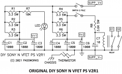
He wrote that it would turn off the relay faster. DIY Sony VFET pt 1
I am trying to figure out how to solve that in reality on the PCB. The 3K6 5W resistors needs to be moved somewhere. And one of the switch holes need to be grounded without a cap in between. Hm.
He wrote that it would turn off the relay faster. DIY Sony VFET pt 1
I am trying to figure out how to solve that in reality on the PCB. The 3K6 5W resistors needs to be moved somewhere. And one of the switch holes need to be grounded without a cap in between. Hm.
Attachments
Last edited:
just put the open ones to gnd and connect to resistor /caps node too but you need the right swich,diverter
Last edited:
- Home
- Amplifiers
- Pass Labs
- DIY Sony VFET pt 2 (N-Channel Build)