I was thinking of gluing a piece of something at the top....wood-stick maybe and using a glue like Tec7. But it is probably not strong enough....
If it was possible to make a notch so a screwdriver could be used.....a Dremel with a small diamond....something....
Drill is out (both which drill bit?) and then fill the hole up with "artificial metal"?
If it was possible to make a notch so a screwdriver could be used.....a Dremel with a small diamond....something....
Drill is out (both which drill bit?) and then fill the hole up with "artificial metal"?
Maybe you can get a hint form youtube that works. Many videos like this:
Removing a broken tap Eight ways to do it - YouTube
Removing a broken tap Eight ways to do it - YouTube
With regard to turn on / turn off thumps, the next vfet version has a relay as part of the power supply filter that shorts the output to ground, this being needed because the n channel circuit has a thump where the p ch version did not.
This same filter board can be fitted to other single ended amplifiers.
My P ch version has a turn off thump,not really loud but its there.Will a bare board be available thru the diy store possibly?
Zen Mod has suggested in other posts to drill a hole all the way
Get Through the heat sink for an m4 nut and bolt-it has worked for me
Get Through the heat sink for an m4 nut and bolt-it has worked for me
Mono no more!
I checked the suspect FE board to make sure that I had installed the jfets correctly (I had), and reflowed all het solderjoints just to make sure.
1. I tested the working FE on the working OS (worked, as expected).
I was now sure I had 1 working FE and 1 working OS.
2. I moved the working FE went to the other heatsink which still had the 2nd OS installed. That channel worked fine too.
I was now sure I had 1 working FE and 2 working OS.
3. I then installed the suspect FE on the first heatsink and was happy to hear that this channel worked fine too.
So, everything is as it should be and I have 2 working FE and 2 working OS.
I am not sure if it was a solder joint or that a wire had not been connected properly or something else that causes the problem, but glad I was able to fix it.
So, both channels working fine now 😀
First impressions on crappy speakers is that it is very nice indeed! A warm sound, but very clear as well.
The next step is to put the case back together and connect the LED, but that will have to wait until Thursday when my helper is here. I will then give it a bit of time to burn in before I do some serious listening.
I will order some decent connectors so that changing FE boards is a bit less of a headache!

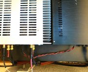
I spent much of the last day replacing the umbilical cord between my linear PSU and the VFET amp. It turned out to be a longer process than anticipated, largely due to using the same style of connectors that are part of the kit SMPS and VFET amp kit.
Here are the parts on Mouser:
https://www.mouser.com/ProductDetai...NKFay3ZyJLw==&countrycode=US¤cycode=USD
https://www.mouser.com/ProductDetai...ArIfKgei5Pg==&countrycode=US¤cycode=USD
The face of power jack is covered by a metal shield that will be in contact with the amp chassis when installed. I did not worry about this, as the corresponding cable shield in the plug is left unconnected. In fact, there is no provision for making a cable shield connection on the plug side.
I used new 18ga silicone wire from ACER Racing. This stuff:
Superworm Silicone Flexible Copper Wire 18 Gauge
– ACER Racing
I was pleasantly surprised to find that it is a better conductor than the generic 16ga NTE stuff that I used to try out the concept. Note that the Kycon plug needs 18ga to build properly, and 16ga will be too large. So the ACER racing wire is very worthwhile. I had to adjust the CapMx circuit in my PSU to compensate for the lower resistance of the umbilical.
All looks very nice and tidy. Almost as if it were meant to be built that way.
Very nice Tungsten...useful information.
I had a Google search tab open for 4 pin DIN connectors and wasn’t sure what would be the best choice.
Although not anxious to change anything right now, I was considering pulling the heatsink and amp board out of one of my F2J monoblocks to test the F1 based power supply with the VFET.
Its not a dual mono setup, but it does have a good size 400VA Antek torroid with dual secondaries. I have the outputs from the F1 CRC PS wired in parallel for each monoblock, but it can be used to power a stereo amp as well.
An umbilical that wouldn’t require any modifications to the VFET would be a requirement for me.
Pics of your new PS wiring would be nice.
Last edited:
Nice work Tungsten! I am a big fan of silicone RC race car or drone / quadcopter wire. Hugh amperage, super flexible, heat resistant, easy to work with, and available in 1 day on Amazon Prime. What could be better? 🙂
The RC race copter folks use Deans connectors which are polarized and good for like 100A.
The RC race copter folks use Deans connectors which are polarized and good for like 100A.
Wayne Colburn of Pass Labs told me about some pretty cool connectors made by JAE. They are stocked by DigiKey but not Mouser. I've provided links below, to a male/female pair that look good for power amplifier use.
Panel mount female socket
Free hanging (inline) male plug
I think it's a very good thing that these are uncommon. Nobody owns any other gear using these connectors, so there can't be any unhappy surprises, when someone accidentally plugs the wrong gizmo into your VFET museum piece and causes it to explode.
- 7 pins: Good for +Vdc, -Vdc, Circuit Ground, Mains Protective Earth, and either redundant wires&pins, or else Reserved For Future Expansion
- 10 amperes per pin
- voltage rating 250V (AC), 350V (DC)
- screw-down connector lock
Panel mount female socket
Free hanging (inline) male plug
I think it's a very good thing that these are uncommon. Nobody owns any other gear using these connectors, so there can't be any unhappy surprises, when someone accidentally plugs the wrong gizmo into your VFET museum piece and causes it to explode.
Those connectors look very good. Similar to the set that I used to prototype the external PSU and umbilical. I wasn’t ready to drill into the backplate just yet. Same spec for voltage, current and screw lock. I got mine at the local electronics surplus store.
Reserved for future expansion:
+HV
+Filament
–Filament
Reserved for future expansion:
+HV
+Filament
–Filament
Those connectors are good and resemble what has been the ubiquitous “Amphenol Mil-Spec circular” connectors used on aircraft, spacecraft, tanks, rockets, etc. waterproof and designed to withstand the rigors of vibration in extreme environment. They take real skill to assemble - there are people who can assemble umbilicals with 30+ wires.
Mil-Spec Type Circulars | Amphenol Aerospace
Mil-Spec Type Circulars | Amphenol Aerospace
Ooh, those look nice! Reasonable pricing, too.
Goodness... I may be swinging back in the direction of a separate PSU chassis once again... one could allocate some of the extra contacts to carry boost voltage for alternative FE boards (or HV for tubes).
If you're willing to test your discipline vs. yet another YouTube rabbit hole (you've been warned!), there is considerable art devoted to the construction of motorsports wiring harnesses... Those mil-spec circular connectors seem to be among the favorites in that industry.
Linkitty-link: Cost-Effective Crimping | Affordable Connectors AND Tools [GOLD WEBINAR] - YouTube
Like this?


Perfect for extreme vibration environments where reliability is a must.
Perfect for extreme vibration environments where reliability is a must.
Last edited:
- Home
- Amplifiers
- Pass Labs
- DIY Sony VFET Builders thread