Hadn't been for the recent posts I would have missed that completely and made magic smoke!
I am taking this extremely slowly and for once it's paying off! LOL
I looked at post #6,7 and I still not get the pin inversion thing.
I am taking this extremely slowly and for once it's paying off! LOL
I looked at post #6,7 and I still not get the pin inversion thing.
Last edited:
one channel is having LU laying on its back on top of heatsink/L bracket, observing Clouds and Sunshine, in chatting company of two mosfets, each having funny glass with little umbrella in it
other channel Lu is having it's back on underside of heatsink/L bracket, seeing just bottom of case; mosfets are in same position as those of other heatsink, chatting, umbrella glass etc.
he tried having glass (if chatting is not possible) but bubblie can't stay in, you know - gravity
🙂
other channel Lu is having it's back on underside of heatsink/L bracket, seeing just bottom of case; mosfets are in same position as those of other heatsink, chatting, umbrella glass etc.
he tried having glass (if chatting is not possible) but bubblie can't stay in, you know - gravity
🙂
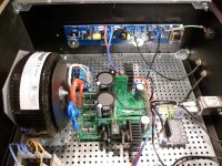
Build finished
Ordinary build using 4U case. Bias current is rock solid. From cold start, it needs almost 2 minutes to reach steady state. After several hours, it will change less than 30 mA.
Offset voltage starts from -60 mV, then during Iq rise, briefly reaches +270 mV and then falls down reaching steady state of +- 10 mV. It does not change more than 20 mV range.
Heatsink temperatures at supply of +- 25 V and Iq 1.5 A are below 40 C.
Nothing left to desire.
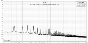
I started measurements with output noise. Unweighted output noise in 22 Hz to 22 kHz bandwidth is 25 uV. That is among best of all FW amplifiers.
Noise is at -110 dB relative to signal level of 1 V rms, so even with super sensitive loudspeakers in quiet room, it won’t be an issue.
Ordinary build using 4U case. Bias current is rock solid. From cold start, it needs almost 2 minutes to reach steady state. After several hours, it will change less than 30 mA.
Offset voltage starts from -60 mV, then during Iq rise, briefly reaches +270 mV and then falls down reaching steady state of +- 10 mV. It does not change more than 20 mV range.
Heatsink temperatures at supply of +- 25 V and Iq 1.5 A are below 40 C.
Nothing left to desire.
I started measurements with output noise. Unweighted output noise in 22 Hz to 22 kHz bandwidth is 25 uV. That is among best of all FW amplifiers.
Noise is at -110 dB relative to signal level of 1 V rms, so even with super sensitive loudspeakers in quiet room, it won’t be an issue.
Attachments


Don’t know jet. It will be a little more in quarantine on the bench, before I will dare to connect it to the proper speakers.
what you did with that Lu tortured with mixed legz?
Although, it was connected the wrong way, there was no damage. Iq was 0.5 A and there was no reaction to adjusting trimpots. So, no big issue if anyone else makes the same mistake.
Soldered new pins and bended them in X fashion, and all is well.
Are the new super drek boards available for the greedy boyz yet?
soon, just to get them
in fact, I can/will send small Lu pcbs with "old" ones too
Although, it was connected the wrong way, there was no damage. Iq was 0.5 A and there was no reaction to adjusting trimpots. So, no big issue if anyone else makes the same mistake.
Soldered new pins and bended them in X fashion, and all is well.

Another interesting observation
DEF amplifiers have unbalanced AC current in positive and negative rails. Ratio is roughly 1:2.7
IIRC with Sissy SIT, current was higher at negative rail. Here is the opposite. It is higher at the positive rail. Could this be the reason for the very low THD, as there is distortion cancelation in play?
long time ago, for DEFiSIT, I wrote that SIT is acting as error correction for mosfet ...... and I was just partially joking
same applies for any OS having dissimilar parts in output, but antiphase currents are case just with SIT and Schade
all other ones I made recently are working in so-so normal PP action
edit: ratio of currents depends of dissimilarity of used parts, practically ratio of their transconductances, so different for each of recent amps
it can be altered by wish, simply using different part where possible ....... I mean - it'll be sacrilege spoiling in any other way ( introducing source resistors) pure Square Law transfer of OS
say - in case where we have IRFP240 present, we can use IRFP150
or , down - we can use IRFP9140, 9240, or FQ or 2SJ
damn, all roads are leading to Wakootalians
Last edited:
Damping factor
Measurement done using two 10 Ω resistors as load at 2.8 V rms output, according to this method:
https://www.diyaudio.com/forums/tubes-valves/354536-measuring-power-amp-output-impedance-2.html#post6206731
Check post #2 as well.
No need for a fancy graph as DF is almost linear in the whole audio bandwidth, starting at 96 @ 20 to 50 Hz, then slowly falling in linearly sloped line ending at DF 83 @ 20 kHz.
Nothing left to desire.
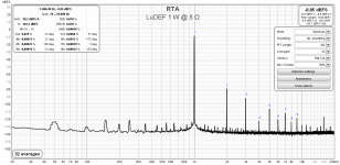
Output power
At 25 V rails, maximum output voltage with no visual distortion is 16 V rms, measured with 5 Ω load.
That is 64 W @ 4 Ω or 32 W @ 8 Ω.
Not bad. 🙂
At 25 V rails, maximum output voltage with no visual distortion is 16 V rms, measured with 5 Ω load.
That is 64 W @ 4 Ω or 32 W @ 8 Ω.
Not bad. 🙂
you can increase them (gate stoppers) without fuss to 220R
one thing - to be sure that LU itself is not behaving badly, only way is to replace it, or to switch them (LU) between channels
if problem goes with LU, that's it
if problem stays with pcb, well, it's rest of circuit
Increased to 200R on 9140 and Iq/Vds were stable when hot, but offset kept drifting.
Put a 100R on the board in series with the SM 100R on the LU and startup went as normal, then the offset took off and went up to 1+V and I shut it down.
Will order some SM 220Rs and be ready to replace the LU I guess.
Lu, quite possible
I see on shipping list that you got them from me
Of course they didn't show anything suspicious in simple sorting procedure
Should I send you replacement, or you have faster option?
I see on shipping list that you got them from me
Of course they didn't show anything suspicious in simple sorting procedure
Should I send you replacement, or you have faster option?
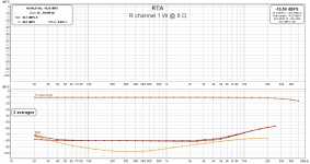
I made distortion measurements as confirmation that no mistakes were made during assembly and following events with one LU connected the wrong way.
Distortion at all power levels is slightly better than posted at the beginning of this thread. That is reasonably to expect for all builds, as ZM is measuring on his breadboard (T-bed) where conditions (PS, wiring) are not optimal. I’ve attached simpler version (H2 and H3 only) of distortion vs. frequency for both channels.
From graph, we can also determine that – 3 dB FR is at 40 kHz.
Attachments

yup
if it works good at T-Bed, it'll work good everywhere
from experience, SQ difference between T-Bed and proper dual mono build is ............ 2 classes/notches/arrow-ranges
🙂
if it works good at T-Bed, it'll work good everywhere
from experience, SQ difference between T-Bed and proper dual mono build is ............ 2 classes/notches/arrow-ranges
🙂
And difference between dual mono and super regulators is another two classes, so I’m in the stratosphere. No wonder I feel dizzy while amp is switched on. 🙂
Lu, quite possible
I see on shipping list that you got them from me
Of course they didn't show anything suspicious in simple sorting procedure
Should I send you replacement, or you have faster option?
Thanks, I do have another pair that I can use one of to try here, might even do that first before ordering SM resistors.
- Home
- Amplifiers
- Pass Labs
- LuDEF