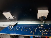
you can mount pcbs parallel, with mosfets in sandwich between heatsink and pcb, with mosfet pins bent adequately - upwards
for that, best to move LU and fix to heatsink separatelly and connect with short wires to pcb
plenty of pics around ...... several here (post #2 and around) Babelfish M25, SissySIT - general building tips and tricks
take pcbs in hands, you'll see wide traces on bottom side , no cutting of pcb please ...... at least not where copper is
I’d be wary of stacking the thermal pads as the heat transfer will be progressively worse for each layer.
Last edited:
Can get away with stacking the LU pads.
LU not putting out a lot of heat and
I've got a metal washer sink on top.
LU not putting out a lot of heat and
I've got a metal washer sink on top.
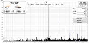
Odd harmonics were high with LU Vds 2.4 V. Some 10 -15 dB below second harmonic(post #657).
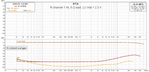
Checking at Vds 2.3 delivers more of triode character. Third harmonic remains 20 dB below second through most of frequency range.
Checking at Vds 2.3 delivers more of triode character. Third harmonic remains 20 dB below second through most of frequency range.
Attachments
ZM was lazy
xeroxed Papa's 2V4 value, too much things were on plate (in fact, still are) to split da hair
that left for cheerful Greedy Boyz

xeroxed Papa's 2V4 value, too much things were on plate (in fact, still are) to split da hair
that left for cheerful Greedy Boyz
Second most important question
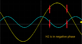
.. in this forum section, after “Will it drive F4?”, seems to be “Is H2 phase negative?”.
Distortion measurement using REW contains phase information and H2 phase is -73°. I’ve put this in perspective using oscilloscope and signal generator. Yellow trace is 1 kHz ‘fundamental’ and blue trace represents 2 kHz ‘harmonic’ shifted exactly -73 degrees, as measured by REW.
We can see that H2 phase is almost perfect negative.
Attachments


in the beginning was the word, and the word was with ZM, then tombo shows the word in a nice wiggly lines. 
From now on, there is no reason for ZM to waste time on measurement of new designs. It is enough for him to declare that sound is spooky and that should be enough for the rest of us.
Let’s check the bottom line on this amplifier. Enough checkboxes are ticked.
All in all, complete Pass.
- Distortion is low.
- It has no NFB.
- Damping factor is greater than 80 for 8Ω load, at any frequency.
- It has high output power even to the 4Ω load (up to 60W no sweat).
- It has adjustable distortion profile or H2 ratio to rest of harmonics.
- H2 phase is negative.
- Noise is very low.
All in all, complete Pass.
Tombo, first, awesome work. Second, please tell us the process for extracting and displaying phase of second harmonic from REW. I’ve been playing with DiAna but would like a second method for comparison.
Well, there is no process at all. REW is awesome tool, even more as it is free.
It has checkbox “Show phase of harmonics” on distortion settings panel and that’s all required.
Thread on how to use REW for distortion measurement was started by xrk971:
Howto - Distortion Measurements with REW
It has checkbox “Show phase of harmonics” on distortion settings panel and that’s all required.
Thread on how to use REW for distortion measurement was started by xrk971:
Howto - Distortion Measurements with REW
Thanks! Been using REW for speaker measurements for a long time. Will look at the distortion measurement capabilities.
Another function of jumper JP101 on ZM’s contraptions called amplifiers
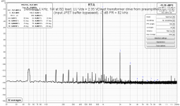
It was mentioned several times, but not often enough, that on ZM’s amplifiers with input transformer, you can drive transformer directly connecting input to the appropriate jumper pin.
While input JFET buffer is very good, we can get better results driving transformer with proper low output impedance preamplifier (Iron Turtle, Salas DCG3, ACP+, …).
What do we get?
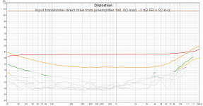
Better frequency response. -3 dB is at 82 kHz in my case.
Lower distortion. With input buffer, distortion was rising toward higher frequency. With direct drive, H2 is at flat level up to 10 kHz, and from that point only slightly rises. But, I don’t care for H2 level past 10 kHz. H3 is 20 – 25 dB below H2 in wide frequency range and closes to H2 level at 10 kHz. But, I don’t care for H3 past 6 kHz frequency. All higher harmonics are at or below noise level.
At 1W, this is very dominant H2, low H3 and nothing else. Well, there is IMD but it is at acceptable levels (0.1 – 0.2 %).
H2 phase is perfect negative through complete frequency range. My rule of thumb is that H2 is good negative if phase is between -120° to -60°. It is better than that. With JFET input buffer, H2 phase is negative only up to 2 – 3 kHz.
My next task is new input buffer that will enable even better results.
It was mentioned several times, but not often enough, that on ZM’s amplifiers with input transformer, you can drive transformer directly connecting input to the appropriate jumper pin.
While input JFET buffer is very good, we can get better results driving transformer with proper low output impedance preamplifier (Iron Turtle, Salas DCG3, ACP+, …).
What do we get?
Better frequency response. -3 dB is at 82 kHz in my case.
Lower distortion. With input buffer, distortion was rising toward higher frequency. With direct drive, H2 is at flat level up to 10 kHz, and from that point only slightly rises. But, I don’t care for H2 level past 10 kHz. H3 is 20 – 25 dB below H2 in wide frequency range and closes to H2 level at 10 kHz. But, I don’t care for H3 past 6 kHz frequency. All higher harmonics are at or below noise level.
At 1W, this is very dominant H2, low H3 and nothing else. Well, there is IMD but it is at acceptable levels (0.1 – 0.2 %).
H2 phase is perfect negative through complete frequency range. My rule of thumb is that H2 is good negative if phase is between -120° to -60°. It is better than that. With JFET input buffer, H2 phase is negative only up to 2 – 3 kHz.
My next task is new input buffer that will enable even better results.
Attachments
Turtle is AVC module, being part of Iron Pumpkin , just to split da hair 🙂
yup, even beefier buffer is possible, but then , tricky to implement that and absolutely necessary ( for intended improvement) proper shunt regs for same ....... there is simply no space in existing form factor
yup, even beefier buffer is possible, but then , tricky to implement that and absolutely necessary ( for intended improvement) proper shunt regs for same ....... there is simply no space in existing form factor
- Home
- Amplifiers
- Pass Labs
- LuDEF