^ Want
How are the signal transformers configured to produce gain, and what is the overall gain of this amp? I’m wondering if an alternate Edcor model might increase overall gain to ~17 dB.
How are the signal transformers configured to produce gain, and what is the overall gain of this amp? I’m wondering if an alternate Edcor model might increase overall gain to ~17 dB.
^ Want
How are the signal transformers configured to produce gain, and what is the overall gain of this amp? I’m wondering if an alternate Edcor model might increase overall gain to ~17 dB.
post #1
Edcor 600:15K, used in M2, can be accomodated in, with some exacto knife and thin wire work
Got it. Thanks 🙂
Front end gain of 2 with autoformer configuration of 600:600 repeater. Can go to gain of 5 with 600:15k and a simple tweak. I think I’m going to want that extra gain, so I have a pair of the 600:15k Edcor units on order.
Wait. Is the standard autoformer gain 4, not 2? That would make more sense, now that I think about it.
Last edited:
classic repeater coil, made as meat of Telephony, is 600R:600R jobbie
majority of them are actually made as each 600R (nominally) winding having CT, so practically being 150R+150R:150R+150R
all included xformers are exactly as that - so see schematic; input tap is one CT, you have one of "150R" to GND, while 3 of them stacked on, then output
that means - 1V in, (1+3)V out
one having "Audio" as part of nick, really doesn't owe to know anything about Telephony........ Telephony generally had lousy audio
Thanks again. Counting coils in the autoformer was confusing me for some reason.
I did manage to make two pairs of VFET amp Bulwark cards with matching gain, even though they used different transformers – Edcor 1:5 and Jensen 1:2. Maybe there is still hope for me.
I remember using rotary dial telephones. So much more fun than the push buttons.
I did manage to make two pairs of VFET amp Bulwark cards with matching gain, even though they used different transformers – Edcor 1:5 and Jensen 1:2. Maybe there is still hope for me.
I remember using rotary dial telephones. So much more fun than the push buttons.
Last edited:
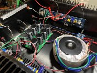
Got my LuDEF build up and running. One channel is rock solid, easy to adjust, no issues. The other starts up the same as the ‘good’ one and adjusts ok, but once it heats up all three measurements on the output stage start fluctuating and offset starts drifting up and down. Both channels make music.
Anything is should be looking at specifically to start? Thanks
Anything is should be looking at specifically to start? Thanks
Hmm, I also have one channel OK and another at -17 V output and with no reaction to any Iq or offset adjustment. Checking voltages, revealed that no current flows through LT3092 (no voltage drop on resistors or Zener diodes) but electrical continuity is OK. Today, I’m receiving a new LT3092 and we’ll see.
What you describe could be a malfunctioning LT3092 CCS.
Zen Mod, you should not stroke your beard while working on boards. It’s an electrostatic generator.
What you describe could be a malfunctioning LT3092 CCS.
Zen Mod, you should not stroke your beard while working on boards. It’s an electrostatic generator.
Got my LuDEF build up and running. One channel is rock solid, easy to adjust, no issues. The other starts up the same as the ‘good’ one and adjusts ok, but once it heats up all three measurements on the output stage start fluctuating and offset starts drifting up and down. Both channels make music.
Anything is should be looking at specifically to start? Thanks
increase gate resistor of IRFP9140
same for LU
how LU is mounted - as intended or with wires?
Hmm, I also have one channel OK and another at -17 V output and with no reaction to any Iq or offset adjustment. Checking voltages, revealed that no current flows through LT3092 (no voltage drop on resistors or Zener diodes) but electrical continuity is OK. Today, I’m receiving a new LT3092 and we’ll see.
What you describe could be a malfunctioning LT3092 CCS.
Zen Mod, you should not stroke your beard while working on boards. It’s an electrostatic generator.
bummer - I can say that every step while soldering and managing them is pretty ESD - free, and this is first one claimed Dodo?!?
certainly less stressed than with common SMD solder-bath .......
I’ll remove board from the case heatsink for easier access and to determine what’s the problem.
I’m not accusing your beard for anything, just joking. Having suspect LT3092, picture of your beard just popped in my mind. 😀
I’m not accusing your beard for anything, just joking. Having suspect LT3092, picture of your beard just popped in my mind. 😀
no worries, accusation not felt, thus not taken 🙂
let me know if I can help in any way, sending LT3092 or whatever
let me know if I can help in any way, sending LT3092 or whatever
you can increase them (gate stoppers) without fuss to 220R
one thing - to be sure that LU itself is not behaving badly, only way is to replace it, or to switch them (LU) between channels
if problem goes with LU, that's it
if problem stays with pcb, well, it's rest of circuit
one thing - to be sure that LU itself is not behaving badly, only way is to replace it, or to switch them (LU) between channels
if problem goes with LU, that's it
if problem stays with pcb, well, it's rest of circuit
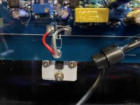
I had to reverse the outer pins of one of the LU1014's since I mounted it flat on a
heat sink and not on a flange like Zenmod.
You might double check the pin connections from the LU1014 to the PCB.
heat sink and not on a flange like Zenmod.
You might double check the pin connections from the LU1014 to the PCB.
Attachments
Last edited:
Thanks - Yeah on the opposite channel (the one that has the opening in the PCB and is working fine from me) you need to flip them if you don't mount on a flange.
It’s alive
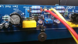
I’m using adapter boards for the LU1014 with vertically soldered pins, so it fits under PCB, but didn’t reverse LU pins on the right channel.
That was the culprit. ZM’s beard is blameless. 🙂
I’m using adapter boards for the LU1014 with vertically soldered pins, so it fits under PCB, but didn’t reverse LU pins on the right channel.
That was the culprit. ZM’s beard is blameless. 🙂

What's the story with reversing pins on the LU?
I'll need to do that eventually... I am stuck with making and tapping holes.
I'll need to do that eventually... I am stuck with making and tapping holes.
Check the pin-out for the LU and ensure that you connect them properly to the PCB.
It may not be 100% intuitive depending on how you orient / mount them. See #633 for one option. See ZMs examples for another option.
It may not be 100% intuitive depending on how you orient / mount them. See #633 for one option. See ZMs examples for another option.
A picture is worth a thousand words. Probably, but few words of warning wouldn’t hurt like: “Pay attention, right channel LU is flip mounted”. Now that this is mentioned several times it is enough of warning. I’m probably not the last one that could make this mistake with the current PCB version and adapter boards.
Meaning of those pictures at posts #6 & #7 didn’t penetrate my thick skull as I just glanced at them. Happily soldering with switched off brain can end with interesting results. 🙂
Meaning of those pictures at posts #6 & #7 didn’t penetrate my thick skull as I just glanced at them. Happily soldering with switched off brain can end with interesting results. 🙂
- Home
- Amplifiers
- Pass Labs
- LuDEF