but how many parts are the minimum to make something sound good?
13 exactly

^
More parts
More transformers
More bias
More HEAT...
.
..13 parts... per channel... plus the power supply... plus the chassis... plus the cooling.... etc, etc... and then you need a 98db/watt speaker. I know, I know, details... I realized I should have added a condition in there... "how many parts do you need to drive a Magnepan?".

Back on topic. I have been corresponding privately with @Goggle1824 and I want to share some of the key points on that amp.
As far as I can tell, I think his amp is the first known case of the ground wire connecting from IEC Earth to chassis!!!
The amp uses DIYAudio store PCB's, dual donuts, and Gianluca's heatsinks. It is perhaps the nicest Rawson build I have seen to date.
The fuse in the unit was a 10A fast blow (default fuse that ships with some of the inexpensive IEC's). He will be installing proper fuses and then powering up.

If it wasn't from the RRR oracle, I wouldn't have believed it.Back on topic. I have been corresponding privately with @Goggle1824 and I want to share some of the key points on that amp.
As far as I can tell, I think his amp is the first known case of the ground wire connecting from IEC Earth to chassis!!!
The amp uses DIYAudio store PCB's, dual donuts, and Gianluca's heatsinks. It is perhaps the nicest Rawson build I have seen to date.
The fuse in the unit was a 10A fast blow (default fuse that ships with some of the inexpensive IEC's). He will be installing proper fuses and then powering up.
A Rawson with proper grounding? Isn't that one of the signs of the apocalypse?
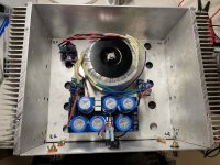
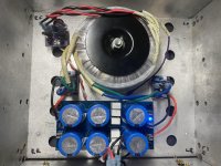
I dug the out chassis that held the non-working F5 from storage. I de-soldered the power supply caps from the home made PCB, checked them, and soldered them to one of Randy's small PS boards. I reinstalled the transformer with new diode bridges. I tried to use as much of the original amp as I could.
Using Randy's power connection PCB with CL-60's and a star ground make setting up the amp much easier and much safer. 24.5V at the PS board.
I'll work on setting up Prasi's layout of the M2 using SMD parts tomorrow. I've also got a pair of finished boards using Juma's F5 layout that might go soon after.
I think use this chassis as my test bed for smaller PCBs. F5m and F6m should fit nicely when Papa's finished with his magic.
Attachments
Will, that looks like the 2x single rail PCB for use in amps like F3. It’s a single rail for each channel. Let me know if you need a dual rail PCB on a similar footprint. CCRC setup with star ground, CL60, and compact footprint for the rawson chassis.
Good call on using the chassis as a test bed or an experimental chassis. If you can, try to mark the heatsink for UMS if it has the appropriate dimensions. Even mark and punch drill holes now, drill and tap as you need them. Else you end up with Swiss cheese, ask me how I know…
One day I’ll make the Juma F5 with FQP’s that I set aside for the project. It’s in the queue, and I have t chassis in mind.
- Home
- Amplifiers
- Pass Labs
- Rawson Repair Reflections