Congrats Rush.
Hopefully, my next amplifier design can be simpler. The SIT3X signal path is fairly simple, but the bias circuits add the lots of complexity.
example of perseverance
")
Thanks Lynn,
If you ever order more boards, put me down for a pair of fcfe boards for my BA3.
I’ll add a separate power supply.
Rush
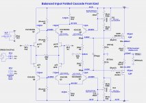
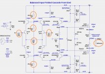
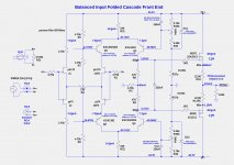
The SIT3X FCFE inverts the signal. In order to preserve absolute phase, the OS outputs must be connected reversed. This works fine, BUT, the relative phase of the second harmonic is now inverted. If the input to the SIT-3X FCFE is inverted, then the signal into the OS is of correct polarity and everything is fine.
Below is a version of the folded cascode front end that has balanced inputs, but only a single-ended output. The input connections can be balanced XLR, RCA (output of same phase as input), and inverted RCA (output phase inverted). The primary negative of this design is the cost of additional 2SK170 and 2SJ74 JFETs. Otherwise it has all of the desired properties.
Attachments
Thanks Lynn,
If you ever order more boards, put me down for a pair of fcfe boards for my BA3.
I’ll add a separate power supply.
Rush
+1...I'd love to get a full set of boards. Thanks Lynn! Awesome work!
According to the DIYAudio Store "40mm Heatsink Information" page 40mm Heatsink Information – diyAudio Store, the 4U 300mm heatsink have a 0.31C/W dissipation rating. If the temperature rise is 25C, the about 80W can be dissipated.
There is a tradeoff between bias current and rail voltage. Ibias*Vrails=Wdiss. If the idle bias current is 1.5A, when the total of the rail voltages can be about 54V.
Bottom line: It can be made to work, but the maximum power output would be lower, the front-end would need to have its own (small) power supply, and some resistor values in the output stage might need to be changed.
no skimping , when building one of the best amps given as Open Source
either build it properly ( saving money with brain, not cutting performance) or don't build it
I'm not trying to be smarta$$ ( which I inevitably am), speaking about my own experience - whenever I cut important corners, later I got cut with those curves
either build it properly ( saving money with brain, not cutting performance) or don't build it
I'm not trying to be smarta$$ ( which I inevitably am), speaking about my own experience - whenever I cut important corners, later I got cut with those curves
This is a great sounding amp.
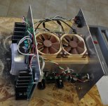
I have a chassis that is between the 5U 300mm and the 5U 400mm (actually about 350mmm). The amp is hot, can't hold my hand on it for more than a second or two.
I ended up a little short on voltage (76Vdc single ended on the OS) and a separate supply +/- 38Vdc, biased at 1.7 amps.
It needs a babysitter, like my SISSYSIT does.
The heatsinks are the most important design limitation Lynn had to build to.
Don't skimp unless you have super efficient speakers and don't need over 20 watts or so.
Rush
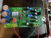
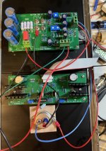
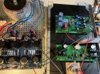
Looking for a little troubleshooting help here. I’ve got one channel built and am following the “Initial adjustments” document.
I’ve verified the power supply as +/- 44 V. When I connect the power supply to the OS and power up using a Variac, I am not getting 0V across node S with P4 and P5 CCW. With just about +/- 6 V coming from the power supply, the voltage across node S is about -2.0V. Increasing voltage any more quickly makes this measurement go more negative.
Measurements of voltage across R22 shows about 100 mV. Increasing the voltage from the power supply will make this value go to 0.2-0.3 Volts and will oscillate a bit up and down.
I’ve attached a few images to show how things are set up.
Any thoughts? Thank you
Attachments
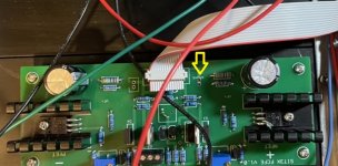
Another voltage to measure is at the node labelled "J1bias" which should be around -10V.
You do not want to get exactly 0V at node S. I usually aim for about -3V. If node S is positive, then the output electrolytic caps will be reversed biased, unless you are using bi-polar electrolytics. There is a long time constant for the bias circuit to stabilize when making adjustments. You should be able to increase the Variac output voltage and keep the voltage at node S above -10V. Of course you also need to keep an eye on the bias current by measuring the voltage across R22. There needs to be some bias current before node S can be measured.
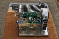
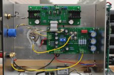
A comment about PCB placement on the heatsinks:
Keep the wire from the OS PCB to the SIT gate as short as possible. I do not know your heatsink dimensions, but this image below shows the PCB placement I used. The SIT and the IXYS PFET are both well placed on the heatsink and the critical wires are kept short.
You do not want to get exactly 0V at node S. I usually aim for about -3V. If node S is positive, then the output electrolytic caps will be reversed biased, unless you are using bi-polar electrolytics. There is a long time constant for the bias circuit to stabilize when making adjustments. You should be able to increase the Variac output voltage and keep the voltage at node S above -10V. Of course you also need to keep an eye on the bias current by measuring the voltage across R22. There needs to be some bias current before node S can be measured.
A comment about PCB placement on the heatsinks:
Keep the wire from the OS PCB to the SIT gate as short as possible. I do not know your heatsink dimensions, but this image below shows the PCB placement I used. The SIT and the IXYS PFET are both well placed on the heatsink and the critical wires are kept short.
Attachments
The SIT3X FCFE inverts the signal. In order to preserve absolute phase, the OS outputs must be connected reversed. This works fine, BUT, the relative phase of the second harmonic is now inverted. If the input to the SIT-3X FCFE is inverted, then the signal into the OS is of correct polarity and everything is fine.
Below is a version of the folded cascode front end that has balanced inputs, but only a single-ended output. The input connections can be balanced XLR, RCA (output of same phase as input), and inverted RCA (output phase inverted). The primary negative of this design is the cost of additional 2SK170 and 2SJ74 JFETs. Otherwise it has all of the desired properties.
Dear Lhquam , could you please tell me what values the resistors marked in red have for the balanced version of FCFE?
Thank you !
Attachments
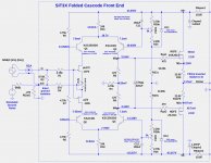
Below is a schematic for the FCFE with the values shown.
A (mostly) complete description of the SIT3X is here: GitHub - lhquam/SIT3X-Power-Amplifier.
A (mostly) complete description of the SIT3X is here: GitHub - lhquam/SIT3X-Power-Amplifier.
Attachments
Vitalica:
Apparently I did not read your question carefully. The schematic you asked about for an FCFE with balanced inputs was from post #722. I have not actually built one of those and I suspect that there will be changes required to a few resistors. Give me some time to look at the simulations again and get back to you.
Apparently I did not read your question carefully. The schematic you asked about for an FCFE with balanced inputs was from post #722. I have not actually built one of those and I suspect that there will be changes required to a few resistors. Give me some time to look at the simulations again and get back to you.
- Home
- Amplifiers
- Pass Labs
- The SIT-3X Amplifier