Hello, I plan to copy your amp in the rca version and I wanna thank you for the work.
I have a question, between the topic and the GitHub directory, what is the reference for the schematics and bom. I think a need to modify the pcb for my heat sink.
I have a question, between the topic and the GitHub directory, what is the reference for the schematics and bom. I think a need to modify the pcb for my heat sink.
Hello I plan to copy the SIT3X in the rca version and I wanna thank you for the work.
I have a question, between the topic and the GitHub directory, what is the reference especially for the schematics and the nom because I think I need to modify the pcb for my heat sink.
I have a question, between the topic and the GitHub directory, what is the reference especially for the schematics and the nom because I think I need to modify the pcb for my heat sink.
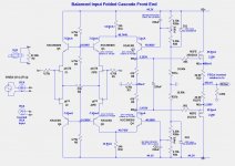
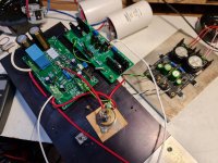
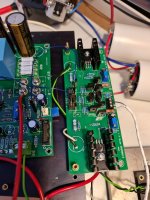
I managed to finish the Balanced version for FCFE.
It works perfectly with divine music!
And very happy that now I have no noise in the speakers, it's completely quiet. With the RCA version I had a little noise.
I still have to work on some adjustments and tests🙂
It works perfectly with divine music!
And very happy that now I have no noise in the speakers, it's completely quiet. With the RCA version I had a little noise.
I still have to work on some adjustments and tests🙂
Attachments

Thanks, ZenMod !
And I wanted a balanced entry because I have a fantastic preamp from you Iron Pumkin 🙂
I'm going to audition for the new SIT3X and Singing Bush.
And I wanted a balanced entry because I have a fantastic preamp from you Iron Pumkin 🙂
I'm going to audition for the new SIT3X and Singing Bush.
I managed to finish the Balanced version for FCFE.
It works perfectly with divine music!
And very happy that now I have no noise in the speakers, it's completely quiet. With the RCA version I had a little noise.
I still have to work on some adjustments and tests🙂
Wow, I am impressed. I didn't expect the untested balanced FCFE to work well without some tweaks, I guess I need to generate a PCB layout for it.
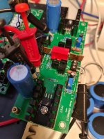
I had some problems with the drift of tensions, but after Lynn gave me some suggestions, now everything is perfect.
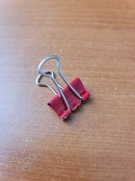
I put a small copper plate between the JFET and fixed it tightly with a small pliers (red piece)
Now all tensions are "dead", not changing by a hundred.
The sound is gorgeous! And once again I want to say - there is total silence in the speakers, I don't even know if the amp is on or not.
Lynn, thank you so much for this amp and for all your help!
I am going to assemble everything in a beautiful case.
Attachments
I am working on a simplified and lower power variant of the SIT3X using cascoded LU1014D JFETs. There are the goals:
I am trying to simplify the folded cascode front end (FCFE) and replace the Toshiba 2SK1013 and 2SJ313 FETs with parts that are more obtainable. The problem with using the Fairchild FQP3N30 and FQP3P20 is their threshold voltages are higher than those of the Toshiba parts, requiring higher rail voltages for the FCFE circuit.
I found some FETs that might work, but they have SMD packages, which might be ok. I think I can reduce their power dissipation to under 1 Watt.
The only other option is to use BJTs (bipolar junction transistors) instead of FETs for the FCFE output buffer.
- 25W into 8R class-A
- The DIYAudio Universal Mounting Spec format board, not longer than 250mm.
- Heatsink power dissipation not greater than 80W per channel.
I am trying to simplify the folded cascode front end (FCFE) and replace the Toshiba 2SK1013 and 2SJ313 FETs with parts that are more obtainable. The problem with using the Fairchild FQP3N30 and FQP3P20 is their threshold voltages are higher than those of the Toshiba parts, requiring higher rail voltages for the FCFE circuit.
I found some FETs that might work, but they have SMD packages, which might be ok. I think I can reduce their power dissipation to under 1 Watt.
- PANJIT PJA138K https://www.mouser.com/datasheet/2/1057/PJA138K-1867329.pdf
- PANJIT PJA3433 https://www.mouser.com/datasheet/2/1057/PJA3433-1867219.pdf,
The only other option is to use BJTs (bipolar junction transistors) instead of FETs for the FCFE output buffer.
I don't know about PANJIT Semiconductor. Those FETs look like they were intended for a fairly different use. May or may not be suitable for high end audio. They have low threshold voltages, what are sometimes called "logic level." Capacitances and total gate charge are also pretty low.
I don't have a problem soldering SOT-23 packages, but these usually have pretty low power dissipation. A better package to look for would be the SOT-223. I have used devices in this package for higher power dissipation in the past, and they work well.
I don't have a problem soldering SOT-23 packages, but these usually have pretty low power dissipation. A better package to look for would be the SOT-223. I have used devices in this package for higher power dissipation in the past, and they work well.
Thanks for the suggestions. The power ratings on all of those small FETs appear to be too low.
Another option that I will investigate is the bootstrap trick used in the FirstWatt F4 to boost the voltage range to the FET gates. That would allow the use of the higher Vgs Fairchild FETs.
Another option that I will investigate is the bootstrap trick used in the FirstWatt F4 to boost the voltage range to the FET gates. That would allow the use of the higher Vgs Fairchild FETs.
I want a source-follower output stage, not a common-source stage. I need the polarity inversion of the folded-cascode. The simplest solution is obviously a separate, small power supply for the folded-cascode front-end. Less than 50mA per channel is needed.
sorry, I didn't read your post thoroughly
just increase rails for few volts 🙂
joking just half ........ I know everything is easy when one can order custom xformers, but when being limited to series production, other story
just increase rails for few volts 🙂
joking just half ........ I know everything is easy when one can order custom xformers, but when being limited to series production, other story
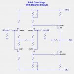
Another simple modification (left for the Greedy Boyz) is to eliminate degeneration and apply negative feedback only to the gain stage itself.
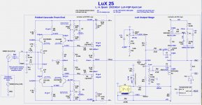
The LuX 25 Amplifier
I finally have a design using the LU1014D JFETs which behaves much like my SIT3X which the Tokin 2SJ182ES SITs, but at a lower power level. Here are to major properties:
25 Watts Class-A.
X-pot to achieve current source behavior of PFET at low power levels.
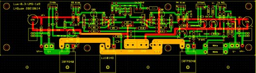
One DIYAudio Universal Mounting Spec. compatible PCB per channel.
+/-24V output stage power rails.
Two small +/-10V power modules to boost the voltage for the folded cascode front end to about +/-31V.
Power dissipation of about 75W-80W per channel.
It required many design iterations over a 4-day period to obtain a satisfactory PCB layout within my allotted board area, but I am fairly satisfied with the result. It still has a lot of parts, but the overall packaging is much simpler than the SIT3X.
I have not yet built this design.
I finally have a design using the LU1014D JFETs which behaves much like my SIT3X which the Tokin 2SJ182ES SITs, but at a lower power level. Here are to major properties:
25 Watts Class-A.
X-pot to achieve current source behavior of PFET at low power levels.
One DIYAudio Universal Mounting Spec. compatible PCB per channel.
+/-24V output stage power rails.
Two small +/-10V power modules to boost the voltage for the folded cascode front end to about +/-31V.
Power dissipation of about 75W-80W per channel.
It required many design iterations over a 4-day period to obtain a satisfactory PCB layout within my allotted board area, but I am fairly satisfied with the result. It still has a lot of parts, but the overall packaging is much simpler than the SIT3X.
I have not yet built this design.
Attachments
- Home
- Amplifiers
- Pass Labs
- The SIT-3X Amplifier