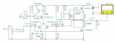

Optimized for 32 Ohm headphones
In the ACP manual Nelson says:
"Of particular note, the gain circuit has been optimized around a 32 ohm load, and performs best at this impedance. Not that it can't drive other loads, as you will see...."
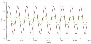
So what can we expect when driving higher impedance headphones like 300 ohm? Different distortion characteristic? How is it different?
In the ACP manual Nelson says:
"Of particular note, the gain circuit has been optimized around a 32 ohm load, and performs best at this impedance. Not that it can't drive other loads, as you will see...."
So what can we expect when driving higher impedance headphones like 300 ohm? Different distortion characteristic? How is it different?
Hi guys I am still wondering where to get one of these boards from as I would like to build one. Cheers.
Please review posts #188, #189, and #199 in this thread.
It is after all Do It Yourself audio.
In the ACP manual Nelson says:
"Of particular note, the gain circuit has been optimized around a 32 ohm load, and performs best at this impedance. Not that it can't drive other loads, as you will see...."
So what can we expect when driving higher impedance headphones like 300 ohm? Different distortion characteristic? How is it different?
Kind of depends on sensitivity as well but in terms of %THD vs Vout, the distortion will be lower into 300 Ohms. However if the sensitivity is lower then the THD per spl might be near the same.
Either way, you can always just throw a 40 to 50 Ohm resistor across the output in parallel with your 300 Ohm headphones to effectively load the output to near 32 Ohms. Plenty of tweaks to try.
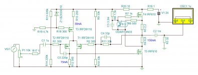
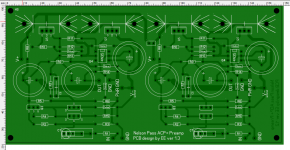
I've designed an alternate PCB for this nice project.
It's a 160*80mm one sided PCB.
If there is interest and Mr.Pass is ok with it then I can post Gerbers too. One proto has been built and the one mistake I had with traces is fixed in this snapshot... (on real thing the fix is hidden under the board") )
)
PS. I left in an option to cut the GND trace and have a dual polarity supply instead to avoid the output cap... have not tried it myself yet though.
It's a 160*80mm one sided PCB.
If there is interest and Mr.Pass is ok with it then I can post Gerbers too. One proto has been built and the one mistake I had with traces is fixed in this snapshot... (on real thing the fix is hidden under the board
)PS. I left in an option to cut the GND trace and have a dual polarity supply instead to avoid the output cap... have not tried it myself yet though.
Attachments
Thank you. I normally buy all my parts from Mouser or DigiKey. I thought they didn't have the J113 but I was looking for "2SJ113". Your suggestion prompted me to look for "J113" and of course found it. Thanks for your guidance!
I'm trying to learn PCB layout and this will be a good project for me.
I appreciate everything I learn from this forum and hope that I can contribute back.
I'm trying to learn PCB layout and this will be a good project for me.
I appreciate everything I learn from this forum and hope that I can contribute back.
Folks:
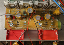
I was one of the fortunate souls who had the opportunity to build an ACP+ at BA19. I've been preoccupied with other projects the last few months but am now installing the board in a chassis and have built a simple linear supply to power it. I used a Hammond 229B34 transformer, wired to provide 17 VAC, but its secondaries are measuring 22.3 VAC unloaded. I'm getting about 28.75 VDC at the caps (again, unloaded). Before I connect the power supply to the ACP+, I gotta ask: should I be concerned?
FYI: the wall wart provided for the ACP+ at BA19 was 24 VDC. I understood acceptable voltages were in the 18 to 24 VDC range.
Regards,
Scott
Last edited:
What type of linear supply? C, CRC, CLC?
You can always load test it first. The current draw is 0.3A or so. I measured mine and it was 0.33A. You can assemble some resistors for a total of 24V/.33A=73R +/-, and 24V x .33A = 7.9W minimum but use 20W total to keep temperature down.
The loaded output voltage will come down, but a test is good for peace of mind.
If the voltage is high, you can always reduce it with the R in a CRC filter.
Ben Mah:
CLC. The power supply consists of the 229B34 followed by four MUR820 diodes and then 8100 uF in caps, a Hammond 155B inductor (6 mH, 0.3R) and another 5400 uF in caps.
Your idea was excellent. If I knew enough to be embarrassed for not having thought of it myself, I'd kick myself. Fortunately, I don't know enough and am grateful for the guidance. With a 75R load, the voltage dropped to 22.6 VDC, which is exactly what I had hoped for.
Sounds great! I'll take some photos and post on the pictures thread.
Thank you!
Regards,
Scott

- Home
- Amplifiers
- Pass Labs
- Amp Camp Pre+Headphone Amp - ACP+