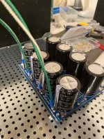
Fried amp update:
- Mosfets replaced—and smoked resistors... Everything fastened down with fancy nylon washers.
- Powered on with bulb tester and 3 DMMs connected—no surprises.
- Powered on without bulb tester and 3 DMMs connected—Not getting any response from R7 and R8 via P1, P2 (zeroed before startup).
- Verified PSU output just to cross something off the list. 26.5VDC+/-
I am able to fiddle P2 and see some DC offset—but getting zero voltage across both resistors regardless of how many turns.......hmmmmm.
Fried amp update:
- Mosfets replaced—and smoked resistors... Everything fastened down with fancy nylon washers.
- Powered on with bulb tester and 3 DMMs connected—no surprises.
- Powered on without bulb tester and 3 DMMs connected—Not getting any response from R7 and R8 via P1, P2 (zeroed before startup).
- Verified PSU output just to cross something off the list. 26.5VDC+/-
I am able to fiddle P2 and see some DC offset—but getting zero voltage across both resistors regardless of how many turns.......hmmmmm.
Similar thing happened to me in one of my monoblocks. I had the P jfet in the N jfet spot and the N jfet in the P spot. Because i used a variac and low voltage, nothing was fried. I swapped them and everything was as it should be. Moral of the story, double, triple check your stuff before moving forward.
I think you may want to check your J-fet's.
Yes... elephant in the room! Toshiba's...
Please check the voltages across the 10 ohm resistors R3 and R4.
Can you also measure the voltages you can get across R5 and R6 as you
crank up P1 and P2?
Yes! I will report back!
Similar thing happened to me in one of my monoblocks. I had the P jfet in the N jfet spot and the N jfet in the P spot. Because i used a variac and low voltage, nothing was fried. I swapped them and everything was as it should be. Moral of the story, double, triple check your stuff before moving forward.
This was a working amp... For the last few months... Then had a catastrophic failure a couple of weeks ago due to a metal washer on the lower PCB mounting holes biting through the solder mask and making contact with the trace...
Thanks guys!
Sorry you are going through some "set backs" pfarrell, mine came early.
Just got to keep on going forward because the other option sucks.
This amp still amazes me with the sound it produces.
Any time I light it up, it turns into a non stop "I want to hear this next" kind of thing.
And all of it is better sounding than anything I have had before.
Just got to keep on going forward because the other option sucks.
This amp still amazes me with the sound it produces.
Any time I light it up, it turns into a non stop "I want to hear this next" kind of thing.
And all of it is better sounding than anything I have had before.
Thanks for the support!
The decision was made today after some further testing and consultations to pull the board and frame it alongside the working channel—yes, I will fab a shadowbox and mount them heroically. I even put back the blown mosfets in all their glory—btw the jfets tested fine.... It will be great. I have procured some replacement already built boards a friend offered up. Which is incredible. So the F5 will live again!
That said... when the F5 boards were offered, it was noted that “...nobody who’s ever built an Aleph J has ever missed their F5...” Haha.
So when does that build start flamethrower? I have to say he’s likely right....also the whole experience was very insightful, more practice with everything, and less dramatic because I have the AJ running daily...

YES! Perfect opportunity for a moment of GRATITUDE.
I couldn't have done any of this with any kind of grace without this forum and some seriously generous and passionate people. It's a testament to Nelson's generosity and grace and those gifts keep giving and providing incredible grounds for all of our exploration. Really, more than amps...
F5? Saved by another great guy we all couldn't explore without—and I like many (most?) will probably end up building all of these amps in one form or another on my search AND then rotate them in and out of use just to experience the ride.... and there's no real end anyway. —but there are some incredible builds you all have made.
Can't love the AJ (or the F5) without each other.
The AJ and F5 will make for a nice comparison/contrast.
And you'll likely build more and rotate them, and find you use some more than
others.
But for me, even the ones I don't use as often are amps that I would be happy
with for long term use. These designs don't disappoint.
And you'll likely build more and rotate them, and find you use some more than
others.
But for me, even the ones I don't use as often are amps that I would be happy
with for long term use. These designs don't disappoint.
I have AJ and F5V3 monoblocks. For my current speakers, Monitor Audio Gold 300 -4 ohms the Aleph J is a bit loose in the bass and runs out of power quickly. The F5V3 can do 400w into 2 ohms and are by far my preferred amp with these speakers. I am running Jensen input transformers on the F5s to get balanced inputs. I recently completed a balanced ba3 front end preamp that has allowed me to run a balanced signal from my DAC. That has lifted my system far above what it was previously.
I am going to try turning up the bias current on the AJ a bit to increase it’s 4 ohm power output. It is only running warm now at about 42c and has some room for more!
I am going to try turning up the bias current on the AJ a bit to increase it’s 4 ohm power output. It is only running warm now at about 42c and has some room for more!
Thanks for the support!
The decision was made today after some further testing and consultations to pull the board and frame it alongside the working channel—yes, I will fab a shadowbox and mount them heroically. I even put back the blown mosfets in all their glory—btw the jfets tested fine.... It will be great. I have procured some replacement already built boards a friend offered up. Which is incredible. So the F5 will live again!
That said... when the F5 boards were offered, it was noted that “...nobody who’s ever built an Aleph J has ever missed their F5...” Haha.
So when does that build start flamethrower? I have to say he’s likely right....also the whole experience was very insightful, more practice with everything, and less dramatic because I have the AJ running daily...
Is that a triple dog dare thing?
Hey Guys,
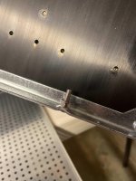
I got an L bracket. I haven't been able to find photos of the bottoms of other people's amps. Do you guys run the screws that hold the L bracket to the chassis through the grid plate AND the black bottom plate of the chassis? Or just the grid plate. Just want reassurance that the grid plate is sufficient to hold the transformer weight.
Thank you!
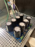
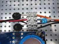
progress pics #1
Here's some progress pics..
You can see the nut and washers I used as spacers to get a better grip on the perforated plate.
Also I didn't put shrink wrap on my CL-60 legs because the black insulation on them went far enough down the legs to cover the exposed wire. Hope that's cool.
I read a bunch of the buzz/hum posts after 6L6 told me not to mount the filter cap board to the front of the chassis. I am following a picture of a build from there (I think it's pfarrell's) which ran the mains under the perf plate from the switch all the way to the very front in an effort to keep every other wire very short and away from the signal wires and amp boards.
Thanks for the continued help!
EDIT: yes yes.. I'm sure my wire colors are concerning.
-Jesse
Attachments
Last edited:


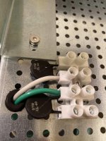
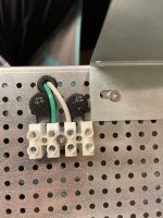
Sadness. I was just following the official build guide pics which showed a plastic connection block. (pic of picture from the guide attached)
Not sure about non-existant clearance. There's as much clearance as the nut, two washers, and edge of the bracket in my pic. I've got my perf plate flipped so the edges point down. Oh maybe you mean clearance from the CL-60s to the perf plate? I guess the insulation on them isn't good? Could I shrink wrap them?
Thanks for the advice.
-Jesse
Attachments
Last edited:
I'm trying to replicate what's going on in the pic on this post:
https://www.diyaudio.com/forums/pass-labs/121228-f5-power-amplifier-1614.html#post5942964
https://www.diyaudio.com/forums/pass-labs/121228-f5-power-amplifier-1614.html#post5942964
dunno for build guide , but plastic and heat don't go well in my book
clearance - there is a 3mm max clearance between black NTC body and base plate
wires are close to NTC body
make it safe ......
besides - that type of connection block is good only for multistrand (litz) wire - solid core wire ( as leads of NTCs are ) is much more compressive/compressible , in time you'll get lousy connection ...... and lousy connection leads to heat and resistance
when you have solid core leads - solder them to eyelets , and eyelets goes under screws of proper connection blocks
plenty of pics with proper , tall - black connection blocks around
- Status
- This old topic is closed. If you want to reopen this topic, contact a moderator using the "Report Post" button.
- Home
- Amplifiers
- Pass Labs
- F5 V3