Ain't DIY grand?? 
And yes, you absolutely built it. All the frustrations are worth it when you sit through, figure it out, and it finally comes together and works perfectly.
😀 😀 😀
I think it bears repeating, thank you Nelson Pass, without your tireless support for this community for many, many years, moments like this wouldn't happen. 🙂


Hey Guys! Merry Christmas!
I'm back on this project.. Building my power supply board. Now with (probably unnecessary) 88KuF per rail.. I didn't want to be left out of the 22k capacitor party, even though every schematic seems to indicate even half of that would work.
I am using the monolithic diode bridges.. which means I'm not using the diode section of the power supply boards. Does that mean I can dispense with thinking about and using input snubbing resisters and capacitors because they are part of the unused diode section? Or do they have to show up somewhere else.
For the output snubbing capacitor I have the .1uF blue square cap and it fits right.. But the 1 ohm 3W resister listed in the BOM is too big for the R11/R12 slot. What do? Is this because I'm using the older BOM for this board?
Other questions:
Can I use a 22k resistor for the bleeder resistor? It's the max resistance specified in the BOM, but theoretically using the max resistance should be for a higher voltage setup.
How do I calculate what resistor I need for the LED on the power supply board?
I have this LED:
Lens Size 5mm, T-1 3/4
Voltage - Forward (Vf) (Typ) 2V
Current - Test 10mA
TLHR6400 Vishay Semiconductor Opto Division | Optoelectronics | DigiKey
Thank you very much!
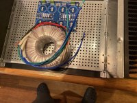
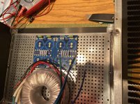
Spacing
Does this spacing look okay? I got the antek 500VA 18v which is a little bigger than the 400VA.. so things are a lil tight. As long as there are a few centimeters between the front faceplate and the transformer it should be okay?
Thanks!
Does this spacing look okay? I got the antek 500VA 18v which is a little bigger than the 400VA.. so things are a lil tight. As long as there are a few centimeters between the front faceplate and the transformer it should be okay?
Thanks!
Attachments
Merry Christmas @jan492 -
re: Input snubbers and monolithic bridges - I wouldn't worry about it, but others may have differing opinions.
22k is fine for the bleeders
R20 and R21 - You can calculate the value to dial in your perfect brightness, or you can toss in something around 10k and rock on.
Spacing looks fine. If you like it better - some put the donuts under a mezzanine plate with the PSU on top or mount the donut vertically. If you mount your PSU board on some standoffs, you'll have a bit more room to tuck a portion of the donut under if you like. I think I've even seen some PSUs on the front plate. Lots of options to free up real estate depending on how you like it.
Merry Christmas all.
Look around the different threads and you will find others who built the F5 in a 4u chassis.
Look at 6L6s build guide he did his pretty much the same way.
I used the deeper 3u chassis and it worked out quite well.
Also, don't limit your searches to just F5 builds, there are some really good things to help you from other threads as well.
I built mine without the snubbers with the advise of others before me.
You wont be disappointed by this amp.
I was/am amazed by what toe tapping, smile on my face, clean, detailed music I am hearing.
A friend of mine (who has this same sickness) said it was "clean, fast and dynamic".
re: Input snubbers and monolithic bridges - I wouldn't worry about it, but others may have differing opinions.
2 1/2 builds in (F5, AJ, M2X monoblocks in process)... I can’t say enough about building Mark’s Quasimodo board/jig and using a scope to calculate input snubber values per transformer. EXTREMELY rewarding process and tons of extra fun working with the DIY diode bridge portion of the PSU. As a noob I learned a ton, got an intro into the scope and several other concepts, and “in theory” maximized sound quality... does it make a difference? I don’t know—haven’t built an amp any other way yet and no A/B comparisons... just building the Quasimodo jig had several new learning experiences for me..
Highly recommended!!! My 2 cents... and Happy Holiday!
You could mount the transformer vertically -
Toroid Corporation > Products > Mounting & Hardware > Vertical > L-Bracket
Toroid Corporation > Products > Mounting & Hardware > Vertical > Omega Bracket
An externally hosted image should be here but it was not working when we last tested it.
Toroid Corporation > Products > Mounting & Hardware > Vertical > L-Bracket
An externally hosted image should be here but it was not working when we last tested it.
Toroid Corporation > Products > Mounting & Hardware > Vertical > Omega Bracket
Fired (fried?) up the F5 today to try with Wayne's pre.... Haven't really listened to it properly since I built the AJ... But I've had it in the system a few times since then as I made mods to AJ...
Hmmmm..... Worked awesome last time I used it... I think I read someplace that someone else had a spontaneous frying after a period of rest on their F5. Guess this is keeping the universe in balance since my Wayne's build went awesome.
???? Bummed. Board fried? Obviously got hot enough to melt the solder—didn't catch it fast enough....BTW an amp about to catch fire makes a washing noise. 😕
Ironically I have a complete F5 kit sitting in a project bin from the last near disaster with it....
Attachments

Did you use keratherm only ?
This was my first non-ACA build... I did use keratherm only per the build guide....think there’s a dissipation issue?
Some sort of catastrophic short, got it. Can that happen over time? If it was Mosfet contact. Should be able to test that before I take it apart....
I don't know if any testing could be reliable, place ceramic tabs then you are sure to eliminate one possible cause
I don't know if any testing could be reliable, place ceramic tabs then you are sure to eliminate one possible cause
Test for continuity between pins and sink? Know a PN off hand for ceramic? Searching Mouser quickly didn't reveal that material option to me...Thanks!
It's just rotten luck for it to work one day and fail the next. Maybe a speck of metal got between?
But before first fire-up the thermal pad insulation should be checked with an ohmmeter between hs and middle pin.
But before first fire-up the thermal pad insulation should be checked with an ohmmeter between hs and middle pin.
Thanks for the PN tooppy!
- Home
- Amplifiers
- Pass Labs
- F5 V3