Booo. I just snapped off a brass standoff in the heat sink. I'm thinking I should use a smaller-than-the-standoff drill bit and drill it out? Alternately, I could try to do crazy glue or something, but it was really tight in there.
Anyone have any ideas?
Thank you!
Anyone have any ideas?
Thank you!
Booo. I just snapped off a brass standoff in the heat sink. I'm thinking I should use a smaller-than-the-standoff drill bit and drill it out? Alternately, I could try to do crazy glue or something, but it was really tight in there.
Anyone have any ideas?
Thank you!
You could... But you need to be exact and then mess around with picks to try to get the pieces out. Better to attempt with these:
https://www.amazon.com/dp/B0002NYBH8/ref=cm_sw_em_r_mt_dp_U_VwPeEb4V4CRWM
Drill a pilot hole—smallest size in that set should work for M3—then the bit is an auger/conical style thread and will in theory bind tight into hole and give you purchase to back out what's left of the threads. Make sure you punch—delicately—the exact center of the threads that are left to get a centered point for drilling the pilot hole...Especially if it's not flat...
Good luck! Bummer that the F5 only has 4 mounting points (AJ has double). Some may disagree—but you might consider just leaving it since you will also have mosfet attachment points.
You don’t really need screws in all the PCB holes. Mosfets plus other holes secured is more than enough.
Thank you! Sounds good as far as just leaving it. It's on the corner that one of the MOSFETs are, so it'll probably be fine, as folks have said.
I may use this opportunity to practice tapping a hole, as there are eight total screw holes on the board itself.. Four of which don't have matching holes on the heatsink... but could!
I may use this opportunity to practice tapping a hole, as there are eight total screw holes on the board itself.. Four of which don't have matching holes on the heatsink... but could!
Have extracted many broke off screws in my life, never one that small though.
For anyone buying a predrilled and anodized heat sink I would recommend getting a bottoming tap for the thread size and cleaning the holes out first.
Those little guys dont like any torque.
For anyone buying a predrilled and anodized heat sink I would recommend getting a bottoming tap for the thread size and cleaning the holes out first.
Those little guys dont like any torque.
Thank you! Sounds good as far as just leaving it. It's on the corner that one of the MOSFETs are, so it'll probably be fine, as folks have said.
I may use this opportunity to practice tapping a hole, as there are eight total screw holes on the board itself.. Four of which don't have matching holes on the heatsink... but could!
I've had really good success with this style of tap:
https://www.amazon.com/dp/B01JSAFB92/ref=cm_sw_em_r_mt_dp_U_9XPeEb07609G8
Seems to be more forgiving to a heavy hand than the typical straight flute style. Note that you should probably also get a single bottoming style tap in M3 to get the extra threads that the above set won't cut.
@jan492
Wellcome to the club, it happen to me also :
F5 made by a complete dummy
M3 is too big, I tried drilling with a 2mm drilbit without success, so I left it alone, the board has now 3 stand-off only but as mentioned above, you have the mosfets, so it is fine.
Actually if someone has a link for true metal stand-off, it would be a good idea, brass is too fragile.
I use nylon standoffs with the threads drilled out so a screw passes through into the heatsink.
I did break off a tap in the heatsink when I was building it because I wasn't using machining lube. So I just moved the board over a bit and drilled new holes.
I did break off a tap in the heatsink when I was building it because I wasn't using machining lube. So I just moved the board over a bit and drilled new holes.
Booo. I just snapped off a brass standoff in the heat sink. I'm thinking I should use a smaller-than-the-standoff drill bit and drill it out? Alternately, I could try to do crazy glue or something, but it was really tight in there.
Anyone have any ideas?
Thank you!
Same thing happened to me. I just left it. Still rock solid with all the other attachment points, including output FETs
When I had broken off a brass standoff in the heatsink, I actually had success with drilling it out with a 2.5 mm drill bit (core size for an M3 thread) and re-tapping the thread.
Surprisingly, that worked ... 😛
I use a tapping set where you have to use three successive taps - coarse, medium, and finisher 😀
No way for drilling out a broken tap in an aluminium heat sink, though ...
Fortunately, with hand-tapping, frequent back-ups to clean the threads, and a drop of tapping fluid for each new pass, that hasn't happened to me.
I feel kind of privileged - my father used to be a toolmaker by trade and taught me a lot when I was a boy. Try to pass something of that on to my boys now ...
Regards, Claas
More questions
Thanks for all the input about my broken standoff.
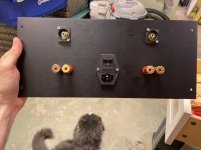
I have decided to mount the filter cap board to the faceplate rather than buy an L bracket for the transformer.
I have a couple more questions..
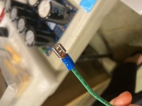
I have a ton of different color 18 gauge silver plated copper stranded wire.. and 30ft of black 16 gauge wire. I have wired up the mains -> switch -> C-60s -> transformer -> rectifier -> cap board all with 12 gauge wire using crimp on female spades.
12 gauge wire won't fit in the amplifier board holes. Can I use 18 or 16 gauge wire to connect the filter cap board to the amp boards? It seems a little flimsy after wiring everything before that with 12 gauge.. I suspect 14 gauge is the largest that would fit in the amp boards... but I don't have any of that.
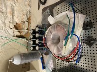
Also, I've never wired a transformer before. Is there any safety I need to know about dealing with them? I know that I'm not supposed to make a circuit around them with the mounting hardware. Anything else? It seems like the plastic they are wrapped in is kinda flimsy and a little bit of wire metal is showing through in one spot.. It's on a part that will eventually be covered up with the rubber mounting thing.
Finally, do I need to use any kind of thermal paste for my monolithic rectifiers on the base grid?
Thank you, as always!
Progress pics attached... sorry about the rotation on some of them. iPhone no play nice with forum software.
-Jesse
Thanks for all the input about my broken standoff.
I have decided to mount the filter cap board to the faceplate rather than buy an L bracket for the transformer.
I have a couple more questions..
I have a ton of different color 18 gauge silver plated copper stranded wire.. and 30ft of black 16 gauge wire. I have wired up the mains -> switch -> C-60s -> transformer -> rectifier -> cap board all with 12 gauge wire using crimp on female spades.
12 gauge wire won't fit in the amplifier board holes. Can I use 18 or 16 gauge wire to connect the filter cap board to the amp boards? It seems a little flimsy after wiring everything before that with 12 gauge.. I suspect 14 gauge is the largest that would fit in the amp boards... but I don't have any of that.
Also, I've never wired a transformer before. Is there any safety I need to know about dealing with them? I know that I'm not supposed to make a circuit around them with the mounting hardware. Anything else? It seems like the plastic they are wrapped in is kinda flimsy and a little bit of wire metal is showing through in one spot.. It's on a part that will eventually be covered up with the rubber mounting thing.
Finally, do I need to use any kind of thermal paste for my monolithic rectifiers on the base grid?
Thank you, as always!
Progress pics attached... sorry about the rotation on some of them. iPhone no play nice with forum software.
-Jesse
Attachments
Just down the road in Salisbury - Toroid Corporation > Products > Mounting & Hardware > Vertical > L-Bracket Mounting the PSU on the front can lead to some noise issues that can only be fixed by moving the transformer to the front...
A little thermal goo is helpful on the bridges, but not strictly necessary.
Transformer mounting is straightforward, use the rubber pads as you surmise. If you think you have a thin part in the wrapping, place a couple layers of good electrical tape on it.
Wire - make what you have work or go buy the right stuff, there’s no wrong answer.
The peeps at Toroid are really nice. I grew up outside Balto and still head that direction on a regular basis—I'd definitely see about a visit and get and L bracket. ~$10 for the largest one. If you use the L bracket make sure the toroid doesn't touch the bottom of the bracket when you mount it.
Good thinking 6L6!
Good thinking 6L6!
It's just rotten luck for it to work one day and fail the next. Maybe a speck of metal got between?
But before first fire-up the thermal pad insulation should be checked with an ohmmeter between hs and middle pin.
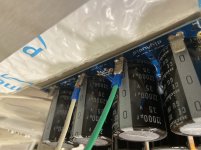
Per this previously unresolved issue—I don't like not having answers and everything "looked" fine... But I found the answer to this catastrophic short... See pic. This after taking the board out and cleaning it and testing the mosfets (roasted)....
Careful with your washers!
Attachments
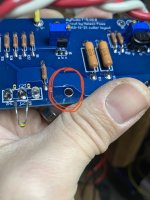
I now see it in your previous picture. Sorry for your loss! Thank you for sharing! Note to self: beware large washers on boards. Nylon washers perhaps. Or none at all.
Yup! I used nylon washers elsewhere, PSUs and AJ build.... Certainly made the connection now—no pun intended—well... maybe 😀
P side shows a little scrape through too...!!
I'll have it back up and running sometime next week.
P side shows a little scrape through too...!!
I'll have it back up and running sometime next week.
Last edited:
@pfarrell - Sorry about your amp, but like @jan492 said, thanks! I'd have never considered looking around the standoff points / posts / washers to make sure they didn't cover / cut into traces. You may help save someone else's amp. I like the idea of the nylon washers.
Yup! I used nylon washers elsewhere, PSUs and AJ build.... Certainly made the connection now—no pun intended—well... maybe 😀
P side shows a little scrape through too...!!
I'll have it back up and running sometime next week.
I'll be checking mine now! I did only use the corner holes. I can see how having the full output shorted would blow it up. Did the Jfets survive?
After reading endless forum pages about ground loops (or some kind of loops) it has been made clear to me that my transformer should be in the front of my amp so that it's not in the middle of anything else. This avoids potential hum. L bracket ordered. If I could do it again, I'd do what flamethrower did and order the 3U 400mm deep chasis and buy a set of good M3 taps.
Nylon washers:
https://www.amazon.com/dp/B07MXBZZN2/ref=cm_sw_em_r_mt_dp_U_Gx3fEbQS1KRWY
Not sure about the Jfets—and they are the not cheap Toshiba's—replace resistors and mosfets and see what's what.
Ground strategy seems to be somewhat of an artform. The only project I've made so far that is dead silent is Wayne's pre (took some poking around with a wire to find the silence... and a nudge from 6L6)... and Mark's Noir HPA (Mostly due to Mark's design IMO).
My F5 was almost silent (L bracket—toroid at front, short 4U)—and AJ has some grounding issues I think... I have some ideas. That's in a full depth 3U.
- Home
- Amplifiers
- Pass Labs
- F5 V3