Okay. Sorry. I gotta ask some dumb questions that I really can't glean from reading past posts... In the startup instructions it says "Place one voltmeter (Set to DC volts) across R12 - to observe DC offset"
What does "across R12" mean? One probe on each side of the resistor? (I doubt it.) If not that, then which side of the resistor? and the black probe to ground?
Second question "dial the pots to 0 ohms." The pots have three wires, 0 ohms on which two wires?
I feel like these are insanely basic.. So I'd be curious how I was supposed to figure it out.
Thank you.
I love popping into the threads to see what new tips I can pick up.
I had been using "large" washers and split washers for all my builds. I've started to make incremental attempts to ensure that should I choose to leave a build in my system for longer than a few months 😀 that it will stand the test of time through a number of thermal cycles and whatever else comes along.
I'm not a fastener expert by any means, but I just looked up "Belleville Washers" - I've never used them before, but based on skimming a few notes on the interwebs, they seem ideally suited to the task.
Picking up a pile for the bench. Thanks for sharing, Jeff!
I just put some of these on my shopping list. @JeffYoung, do you also use a flat washer with the Belleville?
Smoke received. From the two .47 ohm resistors. Was on for about 2 seconds. Saw ~24v from the power supply output before I switched it off. Any ideas? Could I be confused about the orientation of my trimpots? I have them turned all the way counter clockwise except for P3 which I have turned 12.5 turns in.
Thank you for any help! Pics attached. Let me know if there is other info I can provide.
Thank you for any help! Pics attached. Let me know if there is other info I can provide.
Attachments

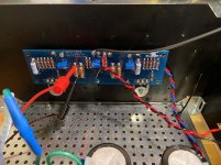
Let me add... that I started by using a dum bulb tester with a 75 watt bulb in it.. The light stayed bright.. Why I proceeded and plugged it into full power.. I cannot answer. Stupidity.. Not understanding what I was seeing. I think I thought that this was probably how it would react to such a low wattage bulb and I didnt have a higher wattage one.
Thank you.
Thank you.
that's the problem. The light has to be bright then goes dim. Bright light all the time indicates some problem.
It happened to me. it keeps bright then I found a swapped N and P Mosfet.
I turned off, and checked and no damage since I did not put full power on.
It happened to me. it keeps bright then I found a swapped N and P Mosfet.
I turned off, and checked and no damage since I did not put full power on.
It's the trim pots being the wrong direction.. Just put them All the way clockwise and 75 watt dim bulb went off after a second..
I'm going to assume you recommend that I get new.47 ohm resistors before I proceed?
I'm going to assume you recommend that I get new.47 ohm resistors before I proceed?
jan492, I did the same thing on my build and was able to just change the .47 resistors and get it running again.
Have been enjoying it for months now and have had no problems.
Have been enjoying it for months now and have had no problems.
Flamethrower,
Yes. I recall that part of this thread. Thank you. I was very happy to see you recovered from it with only having to replace the resistors...
I wonder if I can beg the machine shop guys at work for two .47 ohm 3watt resistors.. (Does wirewound vs metal film matter? Seems like digikey only has vishay wirewound of this spec available..)
I guess I can proceed with the other channel in the meantime...
At least I only have to learn how to use (AND TRUST) a dim bulb tester once.
Thanks guys...
I just put some of these on my shopping list. @JeffYoung, do you also use a flat washer with the Belleville?
Yes. You still want to spread the force exerted by the washer over a large portion of the transistor case.
Cheers,
Jeff.
PS: while it doesn't actually cover Belleville washers, this is the fasteners bible:
Carroll Smith's Nuts, Bolts, Fasteners and Plumbing Handbook (Motorbooks Workshop): Carroll Smith: 9780879384067: Amazon.com: Books
(Carroll Smith was Carroll Shelby's chief mechanic for the Le Mans-winning GT40s.)
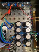
r4 smoked
Sigh. Doing the other side while I wait for new .47ohm resistors... This time R4 smoked during first startup while hooked up to dim bulb tester with 75 watt bulb. Went bright then dim (usually a good sign, right?) but I guess that was enough power to fry the smaller resistors.
Any ideas? Could the DMM probes cause this if i had them in the wrong place?
Thank you..
Attachments
Okay. I see now that Zen Mod's startup instructions (Initial setting of F5 bias--help, please!) from 2011 are for an earlier version of the board. In the earlier version R11 and R12 are the .47ohm 3watt resistors... In version 3 the .47ohm resistors are R7 and R8.. So I guess that's where my probes should be. So the question is, could having my probes on R11 and R12 cause this? I had my probes in the same wrong place on the other side, and despite frying my .47 because of trimpot being turned the wrong way.. R4 did not fry there.
I don't think having the probes across R11/R12 will cause R4 to blow
but I believe R3/R4 may be at risk with large dc offset.
Before power up, did you verify that P1 and P2 are set for minimal resistance?
You can check that by measuring the resistance across R5 and adjust P1 so that
the measured value is small (ideally near zero) (Do the same also with R6 and P2)
but I believe R3/R4 may be at risk with large dc offset.
Before power up, did you verify that P1 and P2 are set for minimal resistance?
You can check that by measuring the resistance across R5 and adjust P1 so that
the measured value is small (ideally near zero) (Do the same also with R6 and P2)
I made the mistake of having P1 and P2 set to the wrong extreme on the other side.. They are set correctly on this side.
Could P3's position cause R4 to smoke? It's really close to it.. I'm not 100% that I set P3 half way. Hoping 2SJ74 is okay..
Halp.
Halp.
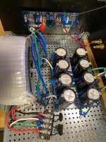
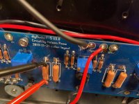
Okay. I think I got one channel doing positive things.. Pic attached.
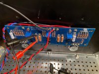
But the other side is still not happy. I checked all the transistors to make sure they were in the right spots, and as best as I can tell they are... Any ideas at all what could smoke R4? Is it some random grounding that is happening somewhere?
Thank you!
But the other side is still not happy. I checked all the transistors to make sure they were in the right spots, and as best as I can tell they are... Any ideas at all what could smoke R4? Is it some random grounding that is happening somewhere?
Thank you!
Attachments

If I look closely at your picture I see a potential "dry joint" on the transistor this could be the cause of your issues. Check the solder joints on the transistors that are bolted to the heatsink as they require more heat to make a good joint.

- Home
- Amplifiers
- Pass Labs
- F5 V3