Absolutely beautiful !!!!😎😎😎😎😎
Congratulations on the build
Enjoy the music -it's a great amp 😀😀😀😀😀😀😀
Congratulations on the build
Enjoy the music -it's a great amp 😀😀😀😀😀😀😀
YES! Some drama!........
FFFugly!
how it sounds now, in stereo, on fancy speaks?
(I don't like that your recessed front is leaving just some thin leftover as bass shoulder)
Oh man... will third time be a charm? Still more drama on right channel zero drama on left. Is it me?
9240 this time, is toast—didn't even get a listen! Ran through all the voltage checks ZM had me do last time—all good. I think—seems like ZM might agree 😀—that somehow the mosfets are getting roasted—maybe replace trimpots? Getting shoddy bias readings? IDK. Will procure 9140—since I don't have any 20K pots either. I will say that biasing took all of 2-3 hours. Had a couple of times when I thought I had stabilization around 180s—went to twiddle offset a TEENY bit from say 50mV, and watched Iq topple to high 150s, low 160s. Okay—lid back on—walk away for 15 min, come back and we'd be at 165... so up Iq... and repeat... a couple of times... soooooo.... While board is out—I'll look over all the joints again.
Also started biasing process without shorting plug in—then added it later (power off, long pause, power back on =) after I thought things were "stable". After adding shorting plug I noted a plunge from 180s to 140s Iq—(just remembered this ZM)—Could that have messed me up???? Gah! Still having fun... but getting a little demoralized. Just excited to hear these amps!
(I don't like that your recessed front is leaving just some thin leftover as bass shoulder)
ZM—monkey coffins? They are SOLID. The woofer flange is basically sitting on the entire thickness (and depth) of the cabinet bottom, right and left—my vertical roundover might be creating an illusion. The Volt mid has no recess, so top flange area of woofer is also SOLID. Plus interior bracing, gaskets and through bolts. Quantum leap for me anyway. Always room for improvement with this Life stuff.
 Can I PLEASE listen to SissySITs?
inputs shorted or not, that's irrelevant regarding setting OS Iq, simply not being DC connected .......
except in case of Gremlins sending Thunderbolts ditto to input, but that's not likely
except in case of Gremlins sending Thunderbolts ditto to input, but that's not likely
Hmmm—I think I understand. However—Adding shorting plug, after an hour, I watched Iq drop from 180ish to 150ish and then twiddled back up Iq from there. That is not possible? Evidence of other issue?
Last edited:
So adding/removing the shorting plug at the inputs changes the readings of the output bias? Sounds like oscillation or noise pickup to me. Do you have a scope?
I always like to bias and dial things in with the inputs grounded (even if theory or ZM says it does not matter).
I always like to bias and dial things in with the inputs grounded (even if theory or ZM says it does not matter).
@ pfarrell - sorry if this has already been addressed - did you measure the Vgs of your SITs yourself at 24V ? I had trouble with mine and it kept blowing fets - ended up that I measured Vgs with a 19V supply but with full rails it was too far out of spec for the circuit to allow it to bias = full story working up to fix in post #510
hope you find the imp, your issue sounds unique but just in case - good luck..dB
hope you find the imp, your issue sounds unique but just in case - good luck..dB
Matthias! Yes, I have a scope. Knowing how to use it properly is another matter 😀. I know enough to use Quasimodo. "Output bias" = negative rail voltage between amp and PSU? There is a lot I don't know, and I can't know what I don't know, yet—the values in mA across the 0R1 series resistor on the Neg voltage leg per ZM biasing instructions on page 1—100% changed when I added the shorting plug after an hour—Or—I watched an immediate drop in Iq. If this was a fluke, I don't know. But it could easily explain how I could have "over biased" the amp—when I saw the drop (I fully expected it to climb back up to where it was, I gave it 15-20 min)... If my readings across the resistor are fishy that could explain both failures—and that would perhaps be Iq trimpot?
I do have one working channel—which leads me to think component issue—though it was only on for 24 hours since it's waiting for its mate. I suppose it's possible the same fault might be in it too—and it's just taking more time—hopefully not. Hindsight being 20/20—I did flag a mental note that on the first audition on the bench, with both channels working for the day playing music—that the right channel seemed warmer than the left, could have imagined that though. Right is one giving trouble. Gonna change both Iq and offset trimmers (I have a 20K here, don't have a 2K, ordering 9140 as well.).... and recheck all the joints etc. Isn't the shorting plug grounding the input?
@dBel84 — I did not measure them myself—they are from the source in Japan that others have bought from—watanabetomoaki—According to the docs that he sent with them—they were measured at 25V, Vgs 2.8. Could be wrong, but I don't know for sure. (loved your build btw.)
gain of input stage is low, buffered stage, so pretty tough to any external noise
however - I'm always putting shorting plugs when powering an amp for setting - been too many times mislead with some tiny noise, while combined with some incompetency of my own
always start with shorted inputs, and feel free to stop doing that only if you're sure that you really have your bench noise-free
watanabetomoaki is good guy and seller; though, I remember he made a mistake measuring SITs with D and S reversed; enough to make me eager to trust only in my own testing
Pras developed exact same procedure for testing as I'm using, and I tested even those got from her
yup, it would be good to pull wires from SIT ( you can leave it on amp sink) and test it .......maybe even to observe its behavior in 5 or so minutes long test
edit: fact of OS Iq difference between shorted/not shorted input leads me to advise thorough exam of all soldering joints etc.
coupling elco (sole Silmic there) and 1uF MKC bypass must prevent any influence between two voltage levels - practically 0V at xformer side and -4V-ish at optocoupler side
Last edited:
Fantastic ZM. Will do. I read all the developments with Pras.... that was entertaining. I’ll do a search for SIT test procedures. Sounds fun. I do have a cheap bench supply.... up to 30V.
regarding SIT biasing voltage - never trust adjustable reg for that, to fiddle with voltage level; use fixed voltage and your own voltage divider/pot
and put 3A fuse in Drain path
and put 3A fuse in Drain path
I have been busy recently and I rarely have time to go online. I still continue to sell 2SK182ES THF-51S TOKIN SIT 2SK76 2SJ26 2SK60 2SJ18 MJ21194 MJ21193 MJ15003 MJ15004 LM350K .............
My mailbox: 378632242@qq.com
I wish everyone good health! Happy family!
My mailbox: 378632242@qq.com
I wish everyone good health! Happy family!
Zen Mod, Is there any strange startup behavior that would prevent me from changing the 3300uF cap across the opto to a 10v vs the 16v you have specified?
Looks like it normally is at about a volt.
I want to use the Elna Silmic II.
Thanks
Looks like it normally is at about a volt.
I want to use the Elna Silmic II.
Thanks
damn
I missed Da Train
I should wrote that you must exclusively use what I wrote as recipe, or else you'll have subpar results ..... Only Parts prescribed by Mighty ZM will bring you Sonic Nirvana!!!

I missed Da Train
I should wrote that you must exclusively use what I wrote as recipe, or else you'll have subpar results ..... Only Parts prescribed by Mighty ZM will bring you Sonic Nirvana!!!

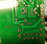
SissySIT R2 pcb error !!!!!!!!!!!!!!
Well, Mea Culpa, maxima!
Just got a word from Chuck B. - he spotted an error on L Channel pcb he just got - R1 and R11 are having touching pads, which is noooooo good
I didn't had that on set of proto/confirmation boards of these and only explanation is that I made unintentional slip/move of R1 (area) in process of making Gerber files, without realizing
As I just wrote to Chuck :
What can I say .... it's embarrassing 🙁
remedy is simple - just take razor knife and make a cut on both sides (top and bottom) between R1 and R11 meeting pads
Sorry again
Attachments

- Home
- Amplifiers
- Pass Labs
- Babelfish M25, SissySIT - general building tips and tricks