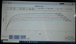
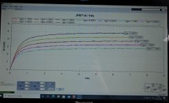
I re-checked my candidates for J113 pairs for IPS#6 boards. I made curve traces on both pairs using the Peak DCR. Attached is an image for both pairs. Each image has curves for both J113 with 5 different Vgs values. Each pair tracks each other curves quite nicely......I think. So I will declare them as pairs and I hope good enough for the purpose.
Attachments
Darrr, don't let small mishaps to frustrate and discourage you! Everything will be all right. Take a break and come back to this a few days later when you are ready. No hi-end name make you as happy listening to a music as the amplifier(s) that you will build yourself. You will make it! No doubt! All the best to you!
Yes, sometimes I lock.
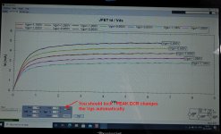
I have tried to figure out when it changes the Vgs.
It will set values during "Identifying" and I did that only for the first J113 in the pair. I think it would only change values if the 2nd J113 in the pair was very different from the first. So if I did the curve tracing with random J113's....it was probably mandatory to "lock". But this time I knew that the two J113 should be very identical.
darr,
I am a new guy too, so I will leave it to others to help with this, but I know it's frustrating when you are sitting there wanting to get started, and have no direction. So here are a couple thoughts....
First, I would simplify... (No softstarts or DC protect circuits or any of that stuff)(Only test one board/channel at a time) I would only put in the circuits which have to be there. Disconnect the supply from everything. Check that both sides of the supply are in spec and have acceptable DC offset. Do they? Okay.. Now, what smoked? Was it Q1 FET? Click here
Next follow the schematic back and test those parts...
I don't want to say to much because I don't know that much, but this will give you a starting point until one of my betters chimes in.
JT
Last edited:

Erratum:
Since there is no short circuit on the mosfet, I compared it with a good one and it behaved the same. I checked with the meter according to the video posted (thanks to thompsontechs) and I find that the desoldered one is good - it works just like in the movie. This, of course, complicates the situation. I will try to check the Mountain View card. I have no other ideas.
Since there is no short circuit on the mosfet, I compared it with a good one and it behaved the same. I checked with the meter according to the video posted (thanks to thompsontechs) and I find that the desoldered one is good - it works just like in the movie. This, of course, complicates the situation. I will try to check the Mountain View card. I have no other ideas.
If Q1 was smoking I would replace it even if it tested good. It might test okay, but be weak. Pull the daughter and set it to the side for now. Replace Q1 and carefully test the DGS voltages of both Q1-Q2. You should see something like G- 5.2v D= 24v (Approx Pos rail voltage) S=.630V or 630mV and for Q2 pretty much the same only with - Neg.
If those voltages are there, the MX2 is working, if not, there is a problem.
JT
If those voltages are there, the MX2 is working, if not, there is a problem.
JT
Can I do these measurements with the bulb tester turned on? I turned on the power supply itself again. Works normally. V+/- 23.7V. The fuse is not blown.I'm connecting the power to a good channel and I check it through the bulb tester(bulb 60W). It slowly fires up more and more, and at the same time led on Mountain View stops shining. I shut down all becouse I don't know how long I can wait to know something is wrong.If Q1 was smoking I would replace it even if it tested good. It might test okay, but be weak. Pull the daughter and set it to the side for now. Replace Q1 and carefully test the DGS voltages of both Q1-Q2. You should see something like G- 5.2v D= 24v (Approx Pos rail voltage) S=.630V or 630mV and for Q2 pretty much the same only with - Neg.
If those voltages are there, the MX2 is working, if not, there is a problem.
JT
Last edited:
My investigation into the case") - new comments.
- new comments.
I was looking for the difference between the channels so I measured the resistors in both boards. R6 and R7 are suspect in the damaged channel, both show the proper value, i.e. 37k4 and 47k On a good channel, the values are about half lower, but during measurements their resistance increases. It may be a clue, but my knowledge is too little to use it. Please suggest what to do next.
- new comments.I was looking for the difference between the channels so I measured the resistors in both boards. R6 and R7 are suspect in the damaged channel, both show the proper value, i.e. 37k4 and 47k On a good channel, the values are about half lower, but during measurements their resistance increases. It may be a clue, but my knowledge is too little to use it. Please suggest what to do next.
What Watt bulb for testing? Here's a little more data for you... I have monos of the MX2 on the bench right now. Like one side of your amp, draws 85 watts at about 1A. Yours will be pulling double that or there abouts...
The slightly lower voltage on Q1 may just be the new FET and an RV1 adjustment.
Check the +- Rail voltage under load. They are most likely the same as your drain voltage. If this is true check the temp of Q1 & Q2 how hot? Not smoking hot, think about increasing the wattage on your bulb. You can do it a step at a time... 60W-75W-100W-150W check voltage at each and make sure nothing is getting to hot.
I have a feeling the amp is operating properly, but doesn't have enough power for the DGS to show working voltages. Now, remember, I'm a new guy too and the only reason I'm trying to help is the others have not responded.
If you can make it to the 150W and nothing smokes, it's time to remove the bulb and fully energize the circuit. Check the values of DGS and tweak RV1
At each step, keep a sharp eye and be ready to snatch the power.
Good luck
Last edited:
Thanks thompsontechs. I'm sure you know more than me.
Oh, it's not easy to get bulbs of this power now I only have 60W. I made the same conditions for a working channel, i.e. without an MV card, input shorted. The voltage readings on the mosfets are the same. In addition, I checked the voltage on the diodes and Q3 legs. There are no differences here either. By the way, I noticed that during the measurement Q3 on pin 6 , the voltage drops and the bulb dims at the same time.
Oh, it's not easy to get bulbs of this power now
I only have 60W. I made the same conditions for a working channel, i.e. without an MV card, input shorted. The voltage readings on the mosfets are the same. In addition, I checked the voltage on the diodes and Q3 legs. There are no differences here either. By the way, I noticed that during the measurement Q3 on pin 6 , the voltage drops and the bulb dims at the same time.
Last edited:
- Home
- Amplifiers
- Pass Labs
- The diyAudio First Watt M2x