Not yet - I have the IEC and terminals mounted in a cardboard box at the moment (4 weeks delivery of the Hammond 1441...
But I have the IEC ground connected to the capacitor on the ground of the input terminals - is that OK, or would I need the chassis tin order to get the right conditions?
But I have the IEC ground connected to the capacitor on the ground of the input terminals - is that OK, or would I need the chassis tin order to get the right conditions?
I have recently emailed Burson and asked the question about running the V5 witout the cover. Burson confirmed the device can operate witout the cover but this will void the warranty. Substituting the nearby caps with the SL6 recommended Nichicon seems a better option to accommodate the beefier Burson.
It seems if you look at picture in post #1859 that even with 220uF/50V caps from kit there is just space enough for a Burson V6. I installed smaller diameter Rubycon 150uF/25V caps and with these there are a lot of space. So if you go for a Burson and not "normal" opamp "rolling" then physical size of the two caps seems not a big issue?
Removing DC input block filter
Hi,
I have no DC offset from my DAC so I am running the Whammy without C1 and C5 on the basis that the best input cap is no input cap. However, is the high pass filter actually made up of C1/C5 and R3/R5 together ? If so can/should I also remove R3/R5 as well as C1/C5 ?
Thanks
Mark
Hi,
I have no DC offset from my DAC so I am running the Whammy without C1 and C5 on the basis that the best input cap is no input cap. However, is the high pass filter actually made up of C1/C5 and R3/R5 together ? If so can/should I also remove R3/R5 as well as C1/C5 ?
Thanks
Mark
Hi,
I have no DC offset from my DAC so I am running the Whammy without C1 and C5 on the basis that the best input cap is no input cap. However, is the high pass filter actually made up of C1/C5 and R3/R5 together ? If so can/should I also remove R3/R5 as well as C1/C5 ?
Thanks
Mark
Jumpering C1 and C5 bypasses the high pass filter. You don't need to bypass R3 and R5.
Loop Breaker Ground Question
Whammy design does not include a loop breaker for circuit ground safety connection. I have seen:
1. Just a capacitor from circuit to chassis ground. 6L6 uses this for his Whammy build. It appears this provides RF grounding but no safety.
2. Wayne's Pearl II RIAA phono preamp PSU example design uses just a 35A bridge for circuit to chassis ground safety. No RF cap in parallel to ground. But it does use a .0033 across the mains hot and neutral.
3. Papa's F5 PSU design uses only a CL-60 thermistor for circuit to chassis ground safety. No RF cap in parallel. But it does use a .0033 across the mains hot and neutral.
4. Elliott Sound (link in earlier post) recommends 3 things: the bridge, the RF cap and a 10 ohm 5 watt resistor (which I suppose could be a CL-60) all in parallel from circuit to chassis ground.
I have built Whammy with just the 6L6 recommended 0.1 RF cap but I am concerned about safety, especially with output jacks. Am I being overly concerned? If not, what is recommended?
It may also depend on the jack connector if it has chassis connection or not. I use a jack which has chassis connection and it is the only signal gnd to chassis I have. I don't know if a 0.1 uF cap from input gnd to chassis would reduce noise (it would have to be measured…...which could be an interesting exercise) but I don't think if you have chassis connection via jack that an e.g. CL-60 from input gnd to chassis would be good as it may introduce a ground loop (hum)?
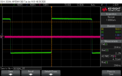
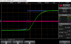
I had access to a scope at work and measured a 10kHz square wave on my Whammy out of curiosity:
Generator signal - Blue (it has a spike which seems to pollute things a bit)
Headphone amp output - Green
Op Amp Vcc+ pin - Purple (AC coupled to see noise)
scope_16.png
scope_14.png
I am happy to see no ringing even with the quite fast op amp OPA2107 and without compensation cap. Apart from that, does this measurement look fine to you?
The amp sounds amazing thanks again for the design.
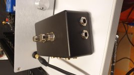
Actually, I am starting a series of Objective Vs Subjective measurements and will develop in a separate thread. I and built an ABX box to be able to blindly switch sources/outputs via guitar pedal push buttons:
20200113_185018.jpg
This way I'll keep a fixed Atom reference and play around with Whammy components until I cannot improve it anymore.
The Whammy is blindly audibly better than a JDS Atom headphone amp, which is reassuring") , but the ABX box is lossy, the amp sounds better without the box in between.
, but the ABX box is lossy, the amp sounds better without the box in between.
Generator signal - Blue (it has a spike which seems to pollute things a bit)
Headphone amp output - Green
Op Amp Vcc+ pin - Purple (AC coupled to see noise)
scope_16.png
scope_14.png
I am happy to see no ringing even with the quite fast op amp OPA2107 and without compensation cap. Apart from that, does this measurement look fine to you?
The amp sounds amazing thanks again for the design.
Actually, I am starting a series of Objective Vs Subjective measurements and will develop in a separate thread. I and built an ABX box to be able to blindly switch sources/outputs via guitar pedal push buttons:
20200113_185018.jpg
This way I'll keep a fixed Atom reference and play around with Whammy components until I cannot improve it anymore.
The Whammy is blindly audibly better than a JDS Atom headphone amp, which is reassuring
, but the ABX box is lossy, the amp sounds better without the box in between.Attachments
Last edited:
Here is a ground isolation circuit. The most important thing is to get a good hard earth ground to your chassis like Jim (6L6) stated. Remember anodizing is insulating so scrape and check with a meter. This circuit will help prevent ground loops yet carry fault currents.
Attachments
Ok.....but the jack connector in the official kit is not isolated and signal gnd will get chassis connection via jack connector. Probably the reason why only a small cap is recommend from input signal gnd to chassis/earth.
Then something like a Neutrik jack connector should be used. I just checked that it has isolated signal gnd.
Then something like a Neutrik jack connector should be used. I just checked that it has isolated signal gnd.
Yes, but not the jack connector for the headphone. Via this connector signal gnd will get chassis connection. It works fine in my setup with no hum ect. as this it may only gnd to chassis connection. I have no earth in outlets so nothing to "polute" signal gnd via chassis. So a direct gnd to chassis works.
The REAN NYS212 is isolated from chassis, has solder lugs and is switching. It’s a very nice jack. NYS212 REAN / Neutrik | Mouser
I'm getting some funky numbers coming out of my opamp. The measured voltages are as follows..
(1) .43 V (8) 16.63 V
(2) 14.8 mV (7) -7.08 V
(3) 13.8 mV (6) 15.2 mV
(4) -16.61 V (5) 13.9 mV
What could be causing this 2OUT (pin7) voltage? I've switched out the socket and tried different opamps that I know are working on a second Whammy that I put together.
As a reference, my other stock Whammy (which is working) measures as follows...
(1) .17 V (8) 16.59 V
(2) 14.8 mV (7) .15 V
(3) 13.8 mV (6) 15.2 mV
(4) -16.66 V (5) 13.9 mV
- Home
- Amplifiers
- Pass Labs
- "WHAMMY" Pass DIY headphone amp guide