@Rafapolit I found another helpful tidbit. @wayne describes the type of capacitor he used in this part of his presentation about the WHAMMY:
https://youtu.be/Mn9jZQwsHmU?t=1687
"And then I couple between the signal ground and that hard chassis ground with a 0.1 uF capacitor. I used a 160V polypropylene XY capacitor, something like 0.2 uF, and everything gets pretty quiet."
https://youtu.be/Mn9jZQwsHmU?t=1687
"And then I couple between the signal ground and that hard chassis ground with a 0.1 uF capacitor. I used a 160V polypropylene XY capacitor, something like 0.2 uF, and everything gets pretty quiet."
About the orange cap
Hi mark60615 and all others,
I'm a long year reader here and have build a few amps, but, as I'm human, I regulary do mistakes. So, anybody please correct me if I'm writing bulls***!")
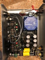
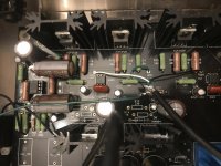
The orange capacitor which you can see on post #2 in the 9th picture and in the last but two:
This cap is NOT a decoupling capacitor. You can see decoupling capacitors in the schematic called C9/C10, or C6/C7 in Salas' DCG3 Preamp here: Salas DCG3 preamp (line & headphone)
The orange cap 6L6 has used is there to have a cleaner audio ground. Please don't mix up audio ground and safety ground: Safety ground has always to be connected to the metal case!
People use resistors, thermistors, diodes and/or capacitors to "isolate/raise/filter" the audio ground (a bit) from the safety ground.
If you use a capacitor, only alternating voltage can pass the capacitor. And: the higher the frequency of the voltage, the easier this voltage can pass the cap, as the cap looks of lower resistance (correctly reactance, because it's frequency dependent) to the voltage -- in comparison to a voltage with a lower frequency.
You can help lower the reactance of a cap for a given frequency by using a bigger capacitor.
Xc=1/(2*pi*f*C)
Xc= capacitive reactance.
pi=π
f=frequencyC=capacitance
Back to our workbench:
In this position the cap shields from (some) of the noise on the safety ground, and it blocks also DC voltage from coming into the Whammy.
Use, like someone mentioned, a cap with a minimum of your used voltage plus a safety margin. 40/50V... and bigger should be fine.
And as "Dielectric" choose polypropylene (PP), Polyester, PET, or even PPS.
It comes handy to use a axial cap in this position, as it makes installing it easier. Have a look of the dimensions before you order, sometimes they are bigger when they arrive than you had imagined!
To calm you down (I remember me reading looking the first time the digikey order page and had my head spinning... So many caps, and I had so less clue! But if you read some basic material about caps, it will help you in the future):
A polypropylene cap is appropriate for the most important place in a piece of audio gear, so it is certainly "good enough" in this position. Also a polyester/PET is fine here, and I guess if you use what's left over on your shelf as 6L6 did, it's also fine. Guess he used an now obsolete Panasonic polyester cap, as this was used a lot in the old Firstwatt amps and also Pass Labs equipment.
Caps with a value of 0,1uF or 0,47uF with voltages of 50/63V are widely used in all sorts of diy projects. Maybe you want to prepare for the next one which is already on the horizon, of cause!
Hope this helps you a bit!
Have fun,
Matthias
Hi mark60615 and all others,
I'm a long year reader here and have build a few amps, but, as I'm human, I regulary do mistakes. So, anybody please correct me if I'm writing bulls***!
The orange capacitor which you can see on post #2 in the 9th picture and in the last but two:
This cap is NOT a decoupling capacitor. You can see decoupling capacitors in the schematic called C9/C10, or C6/C7 in Salas' DCG3 Preamp here: Salas DCG3 preamp (line & headphone)
The orange cap 6L6 has used is there to have a cleaner audio ground. Please don't mix up audio ground and safety ground: Safety ground has always to be connected to the metal case!
People use resistors, thermistors, diodes and/or capacitors to "isolate/raise/filter" the audio ground (a bit) from the safety ground.
If you use a capacitor, only alternating voltage can pass the capacitor. And: the higher the frequency of the voltage, the easier this voltage can pass the cap, as the cap looks of lower resistance (correctly reactance, because it's frequency dependent) to the voltage -- in comparison to a voltage with a lower frequency.
You can help lower the reactance of a cap for a given frequency by using a bigger capacitor.
Xc=1/(2*pi*f*C)
Xc= capacitive reactance.
pi=π
f=frequencyC=capacitance
Back to our workbench:
In this position the cap shields from (some) of the noise on the safety ground, and it blocks also DC voltage from coming into the Whammy.
Use, like someone mentioned, a cap with a minimum of your used voltage plus a safety margin. 40/50V... and bigger should be fine.
And as "Dielectric" choose polypropylene (PP), Polyester, PET, or even PPS.
It comes handy to use a axial cap in this position, as it makes installing it easier. Have a look of the dimensions before you order, sometimes they are bigger when they arrive than you had imagined!
To calm you down (I remember me reading looking the first time the digikey order page and had my head spinning... So many caps, and I had so less clue! But if you read some basic material about caps, it will help you in the future):
A polypropylene cap is appropriate for the most important place in a piece of audio gear, so it is certainly "good enough" in this position. Also a polyester/PET is fine here, and I guess if you use what's left over on your shelf as 6L6 did, it's also fine. Guess he used an now obsolete Panasonic polyester cap, as this was used a lot in the old Firstwatt amps and also Pass Labs equipment.
Caps with a value of 0,1uF or 0,47uF with voltages of 50/63V are widely used in all sorts of diy projects. Maybe you want to prepare for the next one which is already on the horizon, of cause!
Hope this helps you a bit!
Have fun,
Matthias
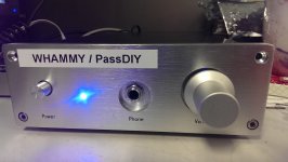
First, I'd like to say thanks to Wayne for sharing his design!
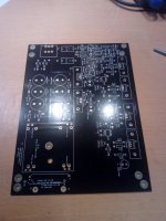
I picked up 3 PCBs to build for friends and family as an Xmas gift
I want to use the OPA2134, but was wondering... do I need the 100pf caps at C2 & C7?
And if so, would these work fine?
And is there anything else I should be aware of including or removing in regards to this op amp?
That being said, I'm curious if there's a particular op amp that Wayne suggests as being most optimal in this circuit.
Thanks!
Last edited:
First, I'd like to say thanks to Wayne for sharing his design!
I picked up 3 PCBs to build for friends and family as an Xmas gift
I want to use the OPA2134, but was wondering... do I need the 100pf caps at C2 & C7?
And if so, would these work fine?
And is there anything else I should be aware of including or removing in regards to this op amp?
That being said, I'm curious if there's a particular op amp that Wayne suggests as being most optimal in this circuit.
Thanks!
Those would work, but you shouldn't need them, I didn't with the same op amp.
I have been wondering the same thing! I would love an answer... but I fear things are never that simple. These type of questions usually get an "it depends" kind of answer where other equipment, type of music, etc. gets involved....That being said, I'm curious if there's a particular op amp that Wayne suggests as being most optimal in this circuit.
Thanks!
Still, a "probably best for most scenarios" would be a very useful answer indeed!
Thanks in advance,
Rafa.
aheck - please post well-lit, in-focus photos of your build and we'll start to look for anything that seems weird.
So, I completely missed this when it posted. Thanks for getting back to me, and I found my problem in that my voltage regulators were switched. Oh well, I hope I learned a lesson. After putting the correct regulators in their correct places, and installing new diodes in case, I’ve traced my incoming DC to my op amp at approximately 15 V, but I’m still only getting a pittance of sound at full volume. The sound is wonderful and clear, there’s just not much of it. The op amp is brand new, you know, just in case i fried it with my backwards installation of regulators. So, what voltage should the MOSFETS be swing in DC and AC at volume? If that’s even what happens at that point, I’m very new to anything like this, so please be gentle. Could there be other issues? I’m good with a meter and I understand simple circuits, this one is a bit over my head for calculation. Again, a few points to check to help troubleshoot would be glorious.
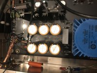
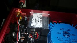
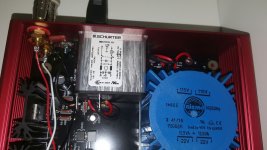
I will also come With this build pretty soon. I have the PCB and most of the parts. Missing chassis and regulators yet. And this will NOT be the mouser partlist build. I walked my own way and ordered parts localy as far as it could be done. Transformer ended up to be a closed 30VA 2x18V(i could not find a good reason to go for the 2x22V option) that will be mountet on the PCB(not a PCB Mount type). All resistors will be thin film 0.6W (and 1W for the PSU filter). also, went for a 10Kohm Alph pot. And i got a 100K on hand just in case. The chassis is a 1907 from ebay, camplete With volumeknob, powerbutten, IEC inlet and predrilled for RCA Connectors. i also ordered a bunch of OP amps. the main OP amp is a AD823. and i also ordered a LM833 and som others. i have 1 consern. The AD823 data sheet says max +/-18V that is pretty Close to the expected +/-16.8V With the diode option. and the i have seen some Reporting that the OP amps are running HOT. so wil it be wise to reduse the voltage to +/-15 and "naked" regulators?
Last edited:
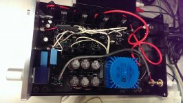
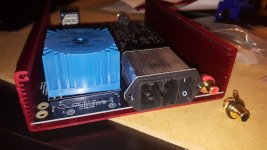
Bob - That looks great! Is that the chassis Cyclotronguy made? Wonderful!
It looks like you have no pot installed and it's jumpered, are you using it like a headphone power amp? Neat!
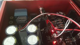
Also, what little edge mounted PCB are in front of the regulator heatsinks? A discrete reg of some sort? I'd love to know more!
It looks like you have no pot installed and it's jumpered, are you using it like a headphone power amp? Neat!
Also, what little edge mounted PCB are in front of the regulator heatsinks? A discrete reg of some sort? I'd love to know more!
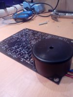
My diyadiostore boards. I did not go for the amgis or.other expencive onboard transformer. I used a 80mm cloced 30VA 18x2 V transformer. And drilled a hole right in the midle of it. (There is NO circuits undrer the the transformer.
Attachments
And lets talk about OP amps. Most have a typical operating voltage of +/-15V. And max +/-18V. At 16.8V (diode option) you are running it Close to Maximum. advantage??? A tiny bit more cuit. Is it Worth it to burn up Your AD 823??? Hell no. Run naked regulators at 15V. if you drive a set of 600ohm headfhones, Then you might get away With the higher voltage. In my case i run 80ohm. it's no dobdt. i run naked regulators and 18V transformer. that wil give me about 29V P-P and +/-8V shaving of the regulators(-1-1.3V loss in filter)
. and if the sinks are up for it, change the 10ohms for 4.7ohm to get 120mA bias insted og 64mA
. and if the sinks are up for it, change the 10ohms for 4.7ohm to get 120mA bias insted og 64mA
Last edited:
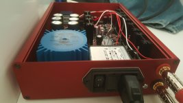
Thanks, here’s a look under the hood...aheck -
Attachments
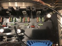
Bob - That looks great! Is that the chassis Cyclotronguy made? Wonderful!
It looks like you have no pot installed and it's jumpered, are you using it like a headphone power amp? Neat!
Also, what little edge mounted PCB are in front of the regulator heatsinks? A discrete reg of some sort? I'd love to know more!
Jim
Cyclotronguy did the box
Headphones are Denon HD5000s anf HiFiMan 500s
The regulators are Sparkos - had them so had to use them.
No volume control - using my XP10 to feed it.
Started with Sparkos discrete op amp - now have Muses01 - WOW
Its going to be hard to move on from Muses but will try others from my collection.
Thanks for your guidance and support
Best
Bob
Sublime
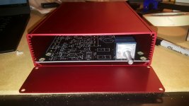
Here's another one in the wild...
I've included some additional pictures to help convey some mounting considerations when using the Hammond case with the diyaudio parts kit.
All components and materials in the kit are first rate. If anything, I may upgrade the 1/4" jack down the road and add some front-facing RCA inputs.
The toughest part of the build was determining the case layout. Once that was finally determined the rest of the build went rather quickly.
The sound coming out of this little guy is sublime. Kudos to Wayne, 6L6 and the diya shop for making this a reality.
Cheers,
Sten
Attachments
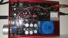
Agree that the connector/switch placement is the hardest part. I bought a nice APEM LED power button for my build and just could not find any good place for it. I ended up with a rectangular switch instead, and had to lay it flat so that it would fit above the caps on both sides of the opamp. Just something to keep in mind.
- Home
- Amplifiers
- Pass Labs
- "WHAMMY" Pass DIY headphone amp guide