Has anyone used a LED Illuminated push-button power switch on their amp?
I like to use this switch on the front panel:
Push Button Stainless Steel with Blue Light Circle 250V 3A O16mm Silver - Audiophonics
The LED is rated 12-24V on the spec sheet. What is the best way to power the switch's LED from this amp's power supply side?
Thank you.
I like to use this switch on the front panel:
Push Button Stainless Steel with Blue Light Circle 250V 3A O16mm Silver - Audiophonics
The LED is rated 12-24V on the spec sheet. What is the best way to power the switch's LED from this amp's power supply side?
Thank you.
You'd just tap into the power post-regulator, connect the other end to neutral. +15-17v would be fine for that.
Wayne-would there be any advantage to using a more advanced Vref in place of the LED?
Nate,
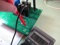
Thank you. So, I can simply tap into these 2 points as indicated by Wayne (see attached pic).
Attachments
I'd have to look at the board layout to recommend an "ideal" spot. That spot looks like it gets a capacitor put over it, scabbing on to the backside with some leads would probably work fine. I'd try to get as physically close to the output of the regs as possible to keep the LED as far from the audio bits as you can. The draw is going to be so minimal that I doubt it matters much where on the rail you tap in.
First of all, thank you so much for the help from all of you. I just returned from Japan for my birthday holiday. budget airlines make my travel so affordable.
The muses op amps at Akihabara are so much cheaper than Mouser....I simply could not resist.
I first lowered the volt rail down to +/-15V by taking away LED/caps+jumpered for the 2 resistors. So far I tried Muses 01 and 02. Muses 01 seems to respond faster and muses 02 is warmer. Muses 8820 & 8920 are also very good but 01 & 02 are cleaner and have more depth+3D. I need to put together an adaptor first before trying muses03.
Most important of all, I found out that FQP-3P20/3N30 FETs give me a HUGE audio improvement. IRF610/9610 FETs are polite and soft; while 3P20/3N30 FET are 100% full of energy and very robust. Love it!
By the way, the super hot 826 op amp was finally damaged. My heat sink came too late. There is distortion at all frequencies now. RIP.
Attachments

Has anyone used a LED Illuminated push-button power switch on their amp?
I like to use this switch on the front panel:
Push Button Stainless Steel with Blue Light Circle 250V 3A O16mm Silver - Audiophonics
The LED is rated 12-24V on the spec sheet. What is the best way to power the switch's LED from this amp's power supply side?
Thank you.
Hi PC997,
I used that exact same power switch. Please see post #293 in the thread.
The easiest and cleanest way was to simply added a feed from R10 & R14 (as they are not used anyway) to the v12 LED (power Switch) with a 4.7K limiting resistor on the R10 +V link side. See below:


Mark.
Last edited:
Most important of all,
I found out that FQP-3P20/3N30 FETs give me a HUGE audio improvement.
IRF610/9610 FETs are polite and soft; while 3P20/3N30 FET are 100% full of energy and very robust. Love it!
Yes, that is also for the famous 2SK2013 and 2Sj313, they are very polite. But the 3P20/3N30 as a follower seems to me also more lively and dynamic.
")
Just to say I have this amp built and it sounds lovely with Muses 8920. might try Muses 01 and OPA627. Running around 90mA
Really nice simple build with terrific results. Listened with HE500 and Focal Elear's. Will get a few pics up later.
Have a few high quality boards left over and a part kit available in swap meet.
Really nice simple build with terrific results. Listened with HE500 and Focal Elear's. Will get a few pics up later.
Have a few high quality boards left over and a part kit available in swap meet.
I'd like my volume pot (20K) to have a more usable range. The amp volume starts at 7:00 o'clock and is unbearably loud by the 10:00 o'clock position. What I'd like to know is what would be the best solution to lowering the gain? Should I raise or lower the resistance of R4 and R8, for example to 2.2K or raise it? I read somewhere that gain is R4/R1+1. So 4.75k/1k+1=5.75 voltage gain. The build guide here states that Gain is set by R8/R12. Lower gain, make R12 bigger, unity gain, R12=10K. I'm so confused.
Should I raise or lower the resistance of R4 and R8, for example to 2.2K or raise it? I read somewhere that gain is R4/R1+1. So 4.75k/1k+1=5.75 voltage gain. The build guide here states that Gain is set by R8/R12. Lower gain, make R12 bigger, unity gain, R12=10K. I'm so confused.
You can either lower the value of R4 or raise the value of R1.
I also use 20KA pot and change the value of R4 / R8 to 3.3K to get lower gain.
Hi PC997,
I used that exact same power switch. Please see post #293 in the thread.
The easiest and cleanest way was to simply added a feed from R10 & R14 (as they are not used anyway) to the v12 LED (power Switch) with a 4.7K limiting resistor on the R10 +V link side. See below:
View attachment 689632
View attachment 689633
Mark.
mbedwani,
Thank you very much for the information.
I'd have to look at the board layout to recommend an "ideal" spot. That spot looks like it gets a capacitor put over it, scabbing on to the backside with some leads would probably work fine. I'd try to get as physically close to the output of the regs as possible to keep the LED as far from the audio bits as you can. The draw is going to be so minimal that I doubt it matters much where on the rail you tap in.
Nate,
Thank you again.
OPA2134 scores way above AD823....far more vocals and mids...although a bit low on Bass compared to 823.
Finally got around to rolling some opamps and I wanted to echo this sentiment. I found the OPA2134 to be a significant upgrade to the AD823. I also tried the LM833, which I did not care for. The 833 sounded muddy to me — not as punchy and accurate as the other two. The AD823 is good, but I found it a bit too forward and fatiguing after I got a taste of the 2134. Didn’t think I could do anything to improve my WHAMMY, yet here we are. Great stuff.
Listening with MD/Sennheiser HD6XX.
Finally got around to rolling some opamps....
Listening with MD/Sennheiser HD6XX.
I've already gone through the LM4562, AD823, OPA627, OPA2134, OPA1612 and have settled on the AD8620. If you have the money for it I would suggest you try it. Sound is clean and tight. Offset voltages came down to -0.2v on both L and R channels too.
- Home
- Amplifiers
- Pass Labs
- "WHAMMY" Pass DIY headphone amp guide