If some is good perhaps more is better
Advanced Interconnections | Decoupling Capacitor DIP Sockets
http://www.farnell.com/datasheets/66800.pdf
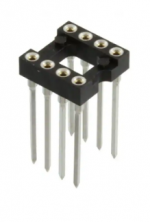
16-Pin DIP IC Socket with 0.1uF Capacitor - $0.15
Advanced Interconnections | Decoupling Capacitor DIP Sockets
http://www.farnell.com/datasheets/66800.pdf
16-Pin DIP IC Socket with 0.1uF Capacitor - $0.15
I agree with your findings and will not be looking for anything other than the Classic to use in my Whammy.
Although the Whammy design already has pretty good power supply caps right at the opamp location, you may want to check out the Burson MKP cap modification, which is a polyester 0.1 cap across the + and - supply rails:
Burson Supreme Sound (SS) Opamp 101 Part 1 (MKP cap tweak) – Burson Audio
Here is how I did it the easy way in post #2911:
"WHAMMY" Pass DIY headphone amp guide
If you have friends on a limited budget that want to get very close to the sound of the Burson Classic, another very large step up from the RC4580 is the OPA1612, which I prefer to the sound of the Vivid. It's what I had settled on before trying the Classic.
Unfortunately, this excellent opamp is only available in a surface mount device package, so an SOIC-8 to DIP-8 adapter board and some fine soldering skills are required. Here is how I did it in post #2009:
"WHAMMY" Pass DIY headphone amp guide
That is a 16 pin version; can't find an 8-pin version there. Did you find one of these?
--Tom
Mark, Tom, AVDG - Thank you!
Tom, your observations are really interesting to me re: the change in performance over time.
AVDG, thank you again for pointing it out and for the links.
Mark, thank you for the information re: "ready-made" parts for this purpose. I'd have certainly never looked or known this was a common part.
From the data I could gather, Advanced Interconnects doesn't offer an 8-pin version, but it is quite possible that I could simply not find one.
From the Farnell link to the E-Tec products, it does seem like a ready-made solution is available.")
Part QIT-308-W001-01 seems to fit the bill for the dual opamp configuration recommended by Burson along with the recommended 100nF => 0,1uF capacitance. I haven't yet found a source. Farnell => Newark shows no parts (at least when I click on the USA link).
One could potentially get some of the $0.15 parts from the link Mark provided. With a relatively small bit of work I could modify it to a nice 8-pin at less expense (I haven't checked shipping).
These seem close, but also not available in 8-pin
https://www.mouser.com/datasheet/2/273/098-259748.pdf
Also, by looking at the parts used in the products provided by Mouser, they're relatively expensive. With an 8-pin adapter (I have a toy boat-load of them) plus some caps and some solder, I think I could put one together. Below are some caps. I chose the search criteria based on the type of cap used in the Mill-Max data sheet. I cut the link from the search and filter criteria I used. I then pasted the link into a new browser window to see if it kept my search criteria. It seems to have worked for me. I hope it carries through.
https://www.mouser.com/Passive-Components/Capacitors/_/N-5g7r?P=1z0wqusZ1z0z819Z1yx4avvZ1y95kbt
Interesting stuff!!!! Thanks again for the insights. It is doubtful I'll get too far into this before the New Year with other projects on the bench, but I'll probably toss a few of the caps in my Mouser cart to go with my next order.
If anyone has further insights, I'm always interested to know if I'm on track, or if I've made a mess of things.

Tom, your observations are really interesting to me re: the change in performance over time.
AVDG, thank you again for pointing it out and for the links.
Mark, thank you for the information re: "ready-made" parts for this purpose. I'd have certainly never looked or known this was a common part.
From the data I could gather, Advanced Interconnects doesn't offer an 8-pin version, but it is quite possible that I could simply not find one.
From the Farnell link to the E-Tec products, it does seem like a ready-made solution is available.
Part QIT-308-W001-01 seems to fit the bill for the dual opamp configuration recommended by Burson along with the recommended 100nF => 0,1uF capacitance. I haven't yet found a source. Farnell => Newark shows no parts (at least when I click on the USA link).
One could potentially get some of the $0.15 parts from the link Mark provided. With a relatively small bit of work I could modify it to a nice 8-pin at less expense (I haven't checked shipping).
These seem close, but also not available in 8-pin
https://www.mouser.com/datasheet/2/273/098-259748.pdf
Also, by looking at the parts used in the products provided by Mouser, they're relatively expensive. With an 8-pin adapter (I have a toy boat-load of them) plus some caps and some solder, I think I could put one together. Below are some caps. I chose the search criteria based on the type of cap used in the Mill-Max data sheet. I cut the link from the search and filter criteria I used. I then pasted the link into a new browser window to see if it kept my search criteria. It seems to have worked for me. I hope it carries through.
https://www.mouser.com/Passive-Components/Capacitors/_/N-5g7r?P=1z0wqusZ1z0z819Z1yx4avvZ1y95kbt
Interesting stuff!!!! Thanks again for the insights. It is doubtful I'll get too far into this before the New Year with other projects on the bench, but I'll probably toss a few of the caps in my Mouser cart to go with my next order.
If anyone has further insights, I'm always interested to know if I'm on track, or if I've made a mess of things.
A Do-It-Yourself alternative is to get a longtail Wire Wrap socket and solder one or more capacitors underneath, yourself. I bet there's room for 3 parallel capacitors: one axial lead and two 2.5mm leadpitch "radial lead" caps. FlagLeft, Torpedo, FlagRight.
DigiKey Product Link
_
DigiKey Product Link
_
Attachments
Last edited:
That is a 16 pin version; can't find an 8-pin version there. Did you find one of these?
--Tom
These look like they will work and you can use a tiny SMD bypass cap to get some SMD practice in.
https://www.amazon.com/DIYhz-Straig...837E3X39ZSM&psc=1&refRID=N5R4HPEWM837E3X39ZSM
https://www.amazon.com/Stargazer-Br...gazer+DIP-8+gold+plated&qid=1606500713&sr=8-2
The good news is that I have some SOIC to DIP-8 adapters from my 'first First Watt' clone. Mark had kindly suggested OpAmp options for the Tucson card. I also have quite a few of the pin headers.
You all have given me a few ideas for how I can get this put together with relatively little effort. Truly appreciated!
SMD soldering, fortunately, has not been an issue thus far. I've done a fair amount, and I have at least a beginner's set of the proper tools. Most importantly, I have magnification. My first was a few of the Schiit Vali minis (AKA the Coaster), then the Norwood card for the M2x. Since then, I've built quite a number of projects requiring SMD work including: several of XRK971's PCA headphone amps, AKA "Altoid" amps; a couple Hakuin prototypes; and a few others that escape me. I actually quite enjoy the SMD work. Even with my poor vision, I find it soothing.
You all have given me a few ideas for how I can get this put together with relatively little effort. Truly appreciated!
SMD soldering, fortunately, has not been an issue thus far. I've done a fair amount, and I have at least a beginner's set of the proper tools. Most importantly, I have magnification.
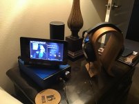
My first was a few of the Schiit Vali minis (AKA the Coaster), then the Norwood card for the M2x. Since then, I've built quite a number of projects requiring SMD work including: several of XRK971's PCA headphone amps, AKA "Altoid" amps; a couple Hakuin prototypes; and a few others that escape me. I actually quite enjoy the SMD work. Even with my poor vision, I find it soothing.Another Wayne Colburn project that hit it out of the park. It is a Roon endpoint running Ropieee with a 7” touch display. Splurged with a OPA2107 was worth it. It is so hard to get out of bed now.
Thanks Wayne and 6L6 for makin it happen.
Bill
Thanks Wayne and 6L6 for makin it happen.
Bill
Attachments
A Do-It-Yourself alternative is to get a longtail Wire Wrap socket and solder one or more capacitors underneath, yourself. I bet there's room for 3 parallel capacitors: one axial lead and two 2.5mm leadpitch "radial lead" caps. FlagLeft, Torpedo, FlagRight.
DigiKey Product Link
_
Then I could stack just two of them and still fit the Burson in between the Nichicon FGs.... I was wondering if something like this existed!
Riki
Another Wayne Colburn project that hit it out of the park. It is a Roon endpoint running Ropieee with a 7” touch display. Splurged with a OPA2107 was worth it. It is so hard to get out of bed now.
Thanks Wayne and 6L6 for makin it happen.
Bill
Awesome
Another Wayne Colburn project that hit it out of the park. It is a Roon endpoint running Ropieee with a 7” touch display. Splurged with a OPA2107 was worth it. It is so hard to get out of bed now.
Thanks Wayne and 6L6 for makin it happen.
Bill
Another Wayne Colburn project that hit it out of the park along with a Roon endpoint running Ropieee with a 7” touch display. Maybe I need to move mine to the bedroom.
 No... I didn't just happen to be listening to Johnny Winter. I do love that album though.

This is pretty common and has happen to me when I built my first Whammy; the pot's outer shell still isn't grounded properly and/or you could also have the RCAs at a different ground potential too. Check that the negative side is connected to the same return point that the pot is. The fact that you said it goes away by taking a test lead/clip and connecting it to your board's return point, as well as that you hear the noise go away when you touch the pot itself (thereby grounding it) proves that the shell isn't returning right. In my case, while I had the pot mounted into the face plate with solid contact, the face plate wasn't actually contacting the sides because the anodizing on all sides of the case panels prevented that. This is why one of my first steps when building anything now is to sand off the anodizing on the mating surfaces of the chassis and then use my DVM to prove I have solid continuity.
With that said, IMHO the most straight-forward solution to your problem is to put your project into a chassis.
Thanks for your response.
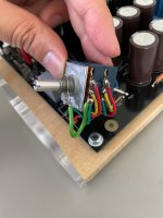
I have fixed my issue by grounding the pot body. I did this by using a conductive ring sandwiched between the pot body and the chassis which has a wire grounding wire attached to it. I then attached this wire to one of the ground pins on pot. See image attached.
Attaching the pot body to circuit ground solves my RF issues.
In doing this I had a thought about safety grounding, should my pot actually be connected to my earth point rather than circuit ground as this would be the case if I had it mounted in a completely conductive enclosure.
Attachments
Last edited:
Thanks for your response.
I have fixed my issue by grounding the pot body. I did this by using a conductive ring sandwiched between the pot body and the chassis which has a wire grounding wire attached to it. I then attached this wire to one of the ground pins on pot. See image attached.
Attaching the pot body to circuit ground solves my RF issues.
In doing this I had a thought about safety grounding, should my pot actually be connected to my earth point rather than circuit ground as this would be the case if I had it mounted in a completely conductive enclosure.
Only connect the board/circuit (and corresponding I/O) to the central return point or you will create a potential alternate return path. Only connect to earth ground through the ground isolator cap (or diode + resistor + cap if you take that approach). I like to think of it as making sure all currents come back to the same return point.
--Tom
I've bought a Whammy! The builder is probably a member on this forum. Excellent work! The sound? Spectacular. I've never heard HD650 or AH-D2000 this dynamic and open. It for sure sounds like an amp costing north of $1000. Heck, even north of $2000!
I never powered HD650 or AH-D2000 with the FirstWatt F6 and Pass INT-150 I had. But its way better then Valhalla 2 and Woo WA6-SE.

I never powered HD650 or AH-D2000 with the FirstWatt F6 and Pass INT-150 I had. But its way better then Valhalla 2 and Woo WA6-SE.
I've bought a Whammy! The builder is probably a member on this forum. Excellent work! The sound? Spectacular. I've never heard HD650 or AH-D2000 this dynamic and open. It for sure sounds like an amp costing north of $1000. Heck, even north of $2000!
I never powered HD650 or AH-D2000 with the FirstWatt F6 and Pass INT-150 I had. But its way better then Valhalla 2 and Woo WA6-SE.
That builder would be me! Very glad that you are happy with it! I use my other Whammy almost every day with a pair of DT 880s.
Trond
Hi All... Well I built my Whammy about 4 months ago and use it everyday in my recording studio and I love it, obviously you all know what it sounds like so no point going on, anyway reason for this post is I'm using a set of 32ohm mix headphones and just wondering if there is any mods I can do as the phones have really low resistance? Any thoughts would be appreciated. Thanks

- Home
- Amplifiers
- Pass Labs
- "WHAMMY" Pass DIY headphone amp guide