sold out already! Must have gone in 60 seconds....
I've put my name in for an email when more become available. They will, won't they? (Bitte!)
Skip
This amp is really not that difficult to make on a proto board. If you are using a laptop PSU and have the fet mounted to the sink, you are only talking about a few resistors, one potti and 2 caps (input output).
This way you are completely flexible to use what ever output cap and input cap. I've build mine on half a euro board (so about 3" x 4"). And on this board is the complete CRC PSU (I've used a standard toroid). This is taking up half the board. The outputcap is a set of 11 small capacitors. And between these 2 big sets of caps is the input cap and all the resistors (including a switch to choose between 2 fets).
If you would use one big output cap and a laptop PSU and stick to just 1 Fet, you could use a tiny, tiny board and solder it in one evening.
Mouser is running low on 193v.
I've used the 159ZC. This one is specified as 60mH@2A. Should be around 50mH when biased with 2.5A
Not as nice as the 193V, but better than the 193T. And easy to get. 🙂
They'll be available any time now. We're just putting some finishing touches on adding them to the store. I encourage you to sign up for the email. 🙂
This amp is really not that difficult to make on a proto board.
That's true, but there are still a lot of DIYers who want a PCB for various reasons, including appearance, convenience, and helping to support the forum we're using right now. 🙂
And, they make great stocking stuffers!

And, they make great stocking stuffers!
I agree that a PCB is a better stocking stuffer than a Hammond 193V. Although I prefer the last one 🙄
Btw: we don't do this stocking stuffing in the Netherlands a lot. Over here it is Sinterklaas (that's where your Santa Claus originated from).
But Sinterklaas is on the 5th of December and we use a huge jute (burlap) bag for the gifts. These are tough. You can put complete amps in them 😀
.... and helping to support the forum we're using right now. 🙂
You are right. Didn't think about that (Dutch cheapskate). Sorry.

I've just fixed this a little for myself (see the little star).
You are right. Didn't think about that...
No problem, Ralph! In fact, I fully encourage the point-to-point approach. I just wanted to make it clear to everyone that the boards will be available soon. They're not actually sold out. 🙂
The boards are available now!
Are they sold as pair or is it 19 USD for one board ?
They're packaged in pairs 🙂
Ordered mine. Can't wait! Thanks again Michael!

When I try to purchase the PCB it wont let me, it says coming soon. Is it not for sale on your blog?
Ordered mine yesterday moments after the email reminder from DIYaudio Store
It was right in the middle of Thor Ragnarok at the cinema 😱
But hey, priorities you know 😀
Cheers Michael!
It was right in the middle of Thor Ragnarok at the cinema 😱
But hey, priorities you know 😀
Cheers Michael!
Tests with 67mH Microwave Inductor
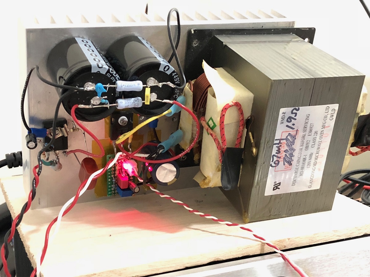
I have been hanging onto a dead microwave oven for 6 years, did not know what was inside that could be useful, but now the time has come. I opened it up to find a beefy inductor which I measured with a DATS2 LCR meter as 67mH and 1.9ohms DCR. I promptly swapped out the two 25w 8ohm parallel resistors for the big fat choke. I set the bias for 1.7amps. I am using a 5amp 24v smps fed through a Juma Easy Peasy cap multiplier (IRFP240) for 19v to the amp.
I was driving this with the Aksa Lender Preamp and source was a Focusrite Solo 2G USB audio interface.
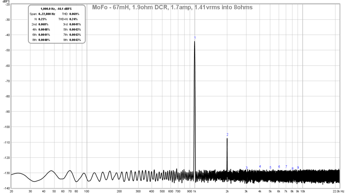
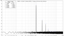
Here are the distortion measurements for 8ohm load.
1.41vrms (0.069% THD):
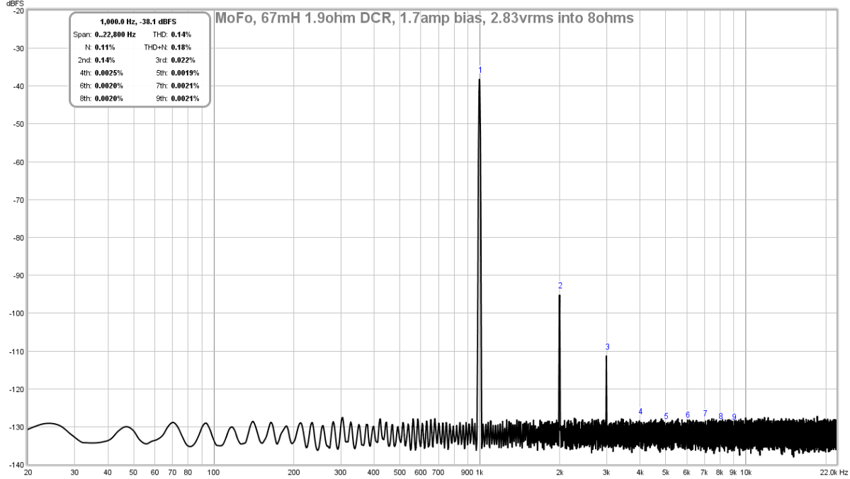
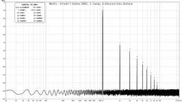
2.83vrms (0.14% THD):
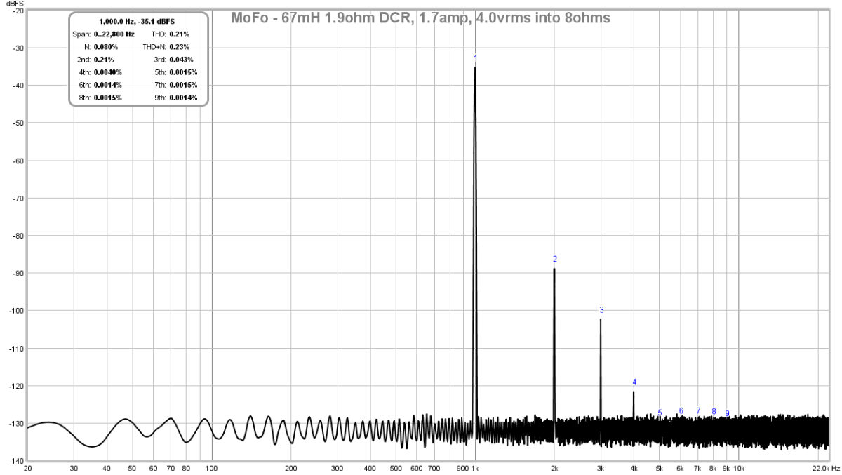
4.00vrms (0.21% THD):
8.00vrms (0.69% THD):

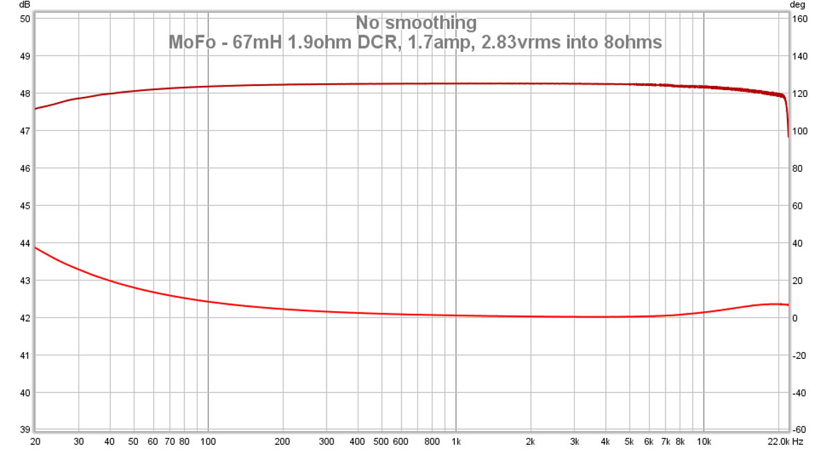
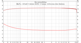
Here is the frequency sweep for 2.83vrms into 8ohms (1dB vertical scale - very flat, maybe -0.5dB at 20Hz):
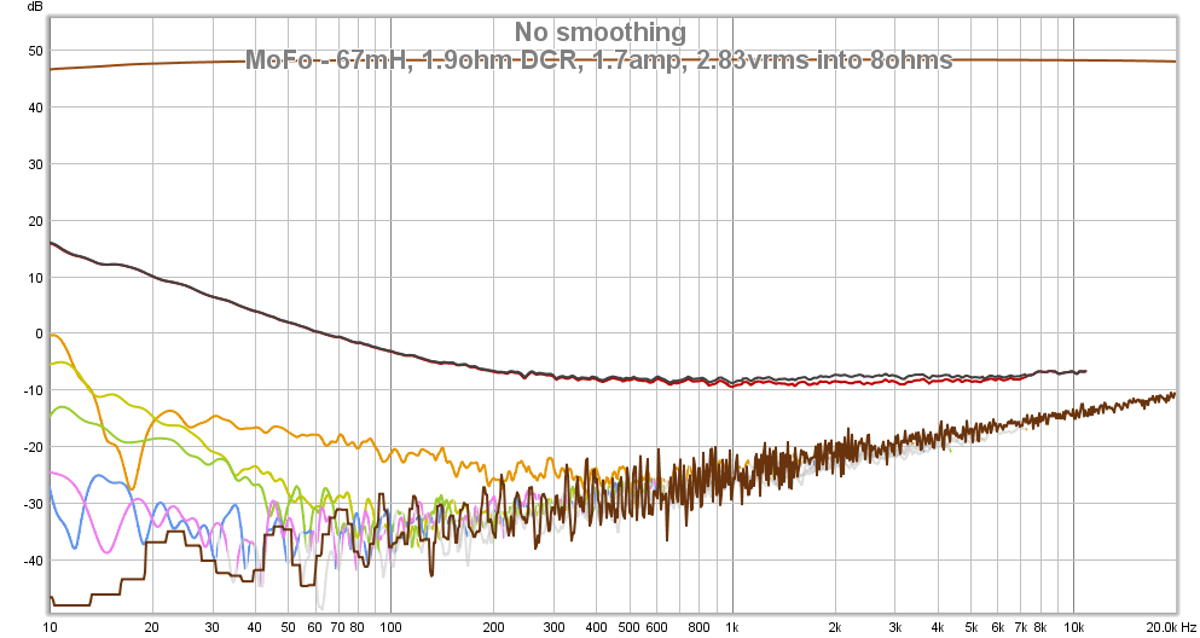
Here are the distortion components vs frequency for 2.83vrms into 8ohms:
The heatsink runs much cooler than when I had the resistors, my 5in x 7in x 1in deep aluminum heatsink runs at 53C on the hotter end and 46C on the cooler end (where the inductor is). Temps measured using IR thermometer aimed at Kapton tape patch to provide enhanced emissivity vs bare aluminum. These are perfectly suitable temperatures.
How does it sound? Very nice, I like it a lot, but then I am predisposed to the SE Class A amp sound. It is a very quiet amp as you can see from the measurements. The use of a SMPS, cap multiplier, and a CRCRC is now my standard practice and eliminates all mains hum.
I have been hanging onto a dead microwave oven for 6 years, did not know what was inside that could be useful, but now the time has come. I opened it up to find a beefy inductor which I measured with a DATS2 LCR meter as 67mH and 1.9ohms DCR. I promptly swapped out the two 25w 8ohm parallel resistors for the big fat choke. I set the bias for 1.7amps. I am using a 5amp 24v smps fed through a Juma Easy Peasy cap multiplier (IRFP240) for 19v to the amp.
I was driving this with the Aksa Lender Preamp and source was a Focusrite Solo 2G USB audio interface.
Here are the distortion measurements for 8ohm load.
1.41vrms (0.069% THD):
2.83vrms (0.14% THD):
4.00vrms (0.21% THD):
8.00vrms (0.69% THD):
Here is the frequency sweep for 2.83vrms into 8ohms (1dB vertical scale - very flat, maybe -0.5dB at 20Hz):
Here are the distortion components vs frequency for 2.83vrms into 8ohms:
The heatsink runs much cooler than when I had the resistors, my 5in x 7in x 1in deep aluminum heatsink runs at 53C on the hotter end and 46C on the cooler end (where the inductor is). Temps measured using IR thermometer aimed at Kapton tape patch to provide enhanced emissivity vs bare aluminum. These are perfectly suitable temperatures.
How does it sound? Very nice, I like it a lot, but then I am predisposed to the SE Class A amp sound. It is a very quiet amp as you can see from the measurements. The use of a SMPS, cap multiplier, and a CRCRC is now my standard practice and eliminates all mains hum.
Attachments
-
 MoFo-67mH-1.7amp-1.41vrms-8ohms-FFT.png83.3 KB · Views: 1,845
 -
 MoFo-67mH-1.7amp-2.83vrms-8ohms-FFT.png84.1 KB · Views: 6,398
 -
 MoFo-67mH-1.7amp-4.00vrms-8ohms-FFT.png82.9 KB · Views: 1,847
 -
 MoFo-67mH-1.7amp-8.00vrms-8ohms-FFT.png84.2 KB · Views: 1,853
 -
 MoFo-67mH-1.7amp-2.83vrms-8ohms-FR.png81.6 KB · Views: 1,851
 -
 MoFo-67mH-1.7amp-2.83vrms-8ohms-HD.png201.4 KB · Views: 2,131
 -
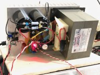 MoFo-with-67mH-uWave-Choke.jpg333.8 KB · Views: 7,085
Last edited:
Update to the MOT above, the DC resistance when measured with the DMM is inaccurate, using the series shunt resistor at the input to the PSU, I measure 1.7amp bias current. Based on that and the 0.820V DC setpoint at the input to the choke, the DCR is thus 0.48ohms - more consistent with what I think others are reporting for a choke of this type and size.
I wonder if adding a series air-core smaller value (bypass) coil will decrease the rising HD as a function of frequency?
I wonder if adding a series air-core smaller value (bypass) coil will decrease the rising HD as a function of frequency?
- Home
- Amplifiers
- Pass Labs
- Build This MoFo!