20k brings it down to 10.5 and 11.5 on tow channels. I can try 30K...
What do you mean by that?sounds fine but can't detect the tube sound at that level.
"sounds fine but can't detect the tube sound at that level."
The whole point is to be able to tune the pre-amp sound by adjusting the volts. IRRC at lower volts there was supposed to be more harmonic distortion leading to a more valve like sound or a more clinical sound at higher volts.
The whole point is to be able to tune the pre-amp sound by adjusting the volts. IRRC at lower volts there was supposed to be more harmonic distortion leading to a more valve like sound or a more clinical sound at higher volts.
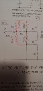
I would like to point out again that the diagram of Papa and the PCB of Diy-Audiostore are different.
Question whether this is relevant?
Thank you.
I reduced the feed from 24.4 to exactly 24 volts with the help of a 4 ohm resistor.
Nevertheless, the cathode voltage remained 0.67V.
Instead of 475 ohms I put in 499, which is 0.613V.
Is that okay?
Many Thanks.
Sorry for Google English, I don't have any others.
Attachments
I finished the amp this morning. I've been trying different voltages on T5 and T6. Started at 9.5V, now at 10v. It will take a while and a lot of listening to decide. It does sound very nice though.
I have 2 issues...
1. There is a serious turn on pop/thump. Is this normal? Is there a fix?
2. I have a low buzz at high volume with no input. It doesn't bother me much as I seldom crank it up that load. But I would like to get rid of it. Any ideas?
Thanks, Morris
I have 2 issues...
1. There is a serious turn on pop/thump. Is this normal? Is there a fix?
2. I have a low buzz at high volume with no input. It doesn't bother me much as I seldom crank it up that load. But I would like to get rid of it. Any ideas?
Thanks, Morris
Am assembling KORG Nutube preamp. Question on orientation of trimmer pots. The ones provided are different from those in picture. The small silver dot on the top of mine will be in the top left corner if I just drop them in with the legs unbent. Or do I need to bend the legs to get that silver dot in the lower left corner as pictured?
Mark Johnson's inline DC filter for SMPS wall warts . Preamps, HPA, Korg NuTube
I'm not sure how many on this thread are aware of Mark Johnson's thread discussing an inline filter of his design for SMPS-powered devices. I agree with his statement that there is definitely a trend toward more devices powered by SMPS these days.
PO89ZB , an inline DC filter for SMPS wall warts . Preamps, HPA, Korg NuTube, etc
What follows is a re-post in that thread of my thoughts on adding this filter to my Pass Korg B1 before and after installation of this particular SMPS filter:
I don't remember exactly when I built the Pass Korg B1, but it was the first version of the board that required a jumper, as one of the traces on the first version of the board was omitted, so I'm guessing I have used and enjoyed my preamp for a year or more. All stock parts from DigiKey, and the board and NuTube from the DIYstore. Pot is a 50k log Alps Blue sourced from Parts Express. My DAC (Topping D70 at the moment) handles source selection (all digital system), and the Triad SMPS recommended in the original BOM was wired directly into the board. I don't like switches or connectors if I can avoid them, so no source selection switch or power inlet barrel connector. Just RCA in and RCA out for removable connections. Housed in an empty SurfacePro box that was sitting next to my workstation. So, nothing fancy (obviously ).
Having spent the ~year with it before filter install, it was very quiet and musical with the pots set at 9.5 volts. I've used 3 or 4 amps with it, and all combinations have seemed to be happy together. Very happy with it, and quite generous once again of Nelson to share his genius.
Nelson spoke a bit about the $9 Triad SMPS in his DIY user's manual as being fairly quiet and cheap, with downstream cap and resistor filtering in the board design improving things further...or something to that effect. I don't have any measuring equipment other than a multimeter, and of course there is expectation bias (especially of something YOU put together--I hesitate to say built because it was such an easy task getting it going), but I honestly didn't think I would notice a difference before/after the filter.
So, I wired the stuffed board, again just soldering the SMPS wires directly to the board's input/output DC pads, and plugged in the SMPS (my way of turning the pre-amp on). And it played music. I am using open baffle speakers in a very small loft area with acoustically treated front walls and front corner traps, with the highest point in the ceiling at 6'4" and knee walls about 3 ft. tall. Even though it is a very small space, it is pretty optimally setup for a good listening space. So I was never lacking in 3d or soundstage width or depth before the in-line filter went in, but all 3 things much to my surprise improved noticeably. Awesome! But what really hit me was how much quieter and punchy the music became. Before, listening at high volumes got a little edgy and confused, but after it went in, my system seemed to demand and welcome you turn it up...just a little more?...
Nothing for me to offer in measurements or 'scope plots, but the filter is staying, and I still stand by my original thought that I posted earlier in the thread that this should be a part of the full kit build in the DIY audio store. Ten bucks (5 for parts and 5 for shipping), plus a board, compliments of konst, is all I have in this, but it elevated my listening experience by many multiples of this cost.
Take care all;
limits
I would like to point out again that the diagram of Papa and the PCB of Diy-Audiostore are different.
Question whether this is relevant?
I reduced the feed from 24.4 to exactly 24 volts with the help of a 4 ohm resistor.
Nevertheless, the cathode voltage remained 0.67V.
Instead of 475 ohms I put in 499, which is 0.613V.
Is that okay?
A. Not relevant.
B. Totally OK.
")
I completed my kit this past weekend. First thing I noticed was that my nutube was extremely microphonic. My wife came down yelling that my music was too loud. Immediately my nutube started to ring. Once the ringing started it would keep on ringing for a long time, presumably due to mechanical feedback that sustained it.
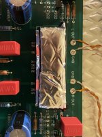
I spent some time trying to tame the microphonic. I tried the rubber stand-offs and lining the interior chassis with noico. It only helped a little with the lid open. The biggest improvement came from wrapping the nutube with noico (I used three layers, see picture). With the lid closed (also lined with noico underneath) I think I'm now in a reasonable shape.
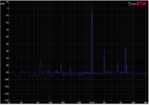
I suspect the ringing came from some mechanical resonance inside the nutube. The frequency of the ringing was very consistent, and was always at 6.5 KHz (sometimes I also see a 4.2 KHz peak, but the 6.5 KHz is always there, regardless of how I tapped the nutube). The second picture shows a 1 KHz signal plus its 2nd harmonic. The peaks at 4.2 KHz and 6.5 KHz came from the ringing.
I spent some time trying to tame the microphonic. I tried the rubber stand-offs and lining the interior chassis with noico. It only helped a little with the lid open. The biggest improvement came from wrapping the nutube with noico (I used three layers, see picture). With the lid closed (also lined with noico underneath) I think I'm now in a reasonable shape.
I suspect the ringing came from some mechanical resonance inside the nutube. The frequency of the ringing was very consistent, and was always at 6.5 KHz (sometimes I also see a 4.2 KHz peak, but the 6.5 KHz is always there, regardless of how I tapped the nutube). The second picture shows a 1 KHz signal plus its 2nd harmonic. The peaks at 4.2 KHz and 6.5 KHz came from the ringing.
Attachments
Thanks for the pointer. Would 400 ohm be a good value?
I figured the heater would draw (9.1-0.6)/475 A = 18 mA, while the 270 ohm resistor draws (23-9.1)/270 A = 51 mA. So we have 33 mA going into the zener, and it'll dissipate 0.3 W. Using a 400 ohm resistor reduces the current through the zener to 35 mA, so the zener should dissipate only 0.15 W (i.e., half the power).
The datasheet says the zener is rated at 200C and 1W, so we're probably okay even in a sealed enclosure. What do you think?
Thanks again.
- Home
- Amplifiers
- Pass Labs
- B1 with Korg Triode