to Suppersready #5338
Your powersupply should work. The B1 - Nutube - pre needs around 60mA of current. Most important is at start-up, till the caps are loaded.
Check copy from Nelson Pass' B1-NUTUBE- article:
The power source is a “wall wart” type external supply, providing regulated 24V and rated at 0.50 Amps current. The preamp will draw about 60 mA in operation, although the extra current rating of the switching supply gives us the initial current to charge the filter capacitors at turn-on. As some switchers have protection which prevents the charging of the caps, it is important to test the specific power supply with the circuit. The specified Triad supply meets this requirement, and is cheap and fairly quiet.
Greets
Dirk
That looks great to me 🙂
Claude
Me too. Any completed B1K that makes someone's ears happy is a win.
300mA are rather on the thin side... sure it is not more?
Claude
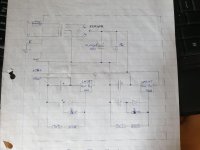
I would think it is. The transformer looks big enough to power a small power amp. I've attached a schematic I drew up quite a while ago. The capacitors in the regulator circuit are 10uF/35V tantalum. The diodes are UF4006.
cubicincher - Thanks for the reference to NP's article. I can't see that there will be problem using the SNAPS based on that.
I've just been notified that the kit should be delivered tomorrow, so I will be finding out very soon. It's going to be very interesting to compare the SNAPS to the wall wart.
Attachments
If the transformer is that big, it should all be fine.
It will be an interesting comparo - just as a side note, I got excellent results with the SMPS + Mark's SMPS filter, perhaps a low cost experiment worth a try
Enjoy this amazing unti very much
Claude
It will be an interesting comparo - just as a side note, I got excellent results with the SMPS + Mark's SMPS filter, perhaps a low cost experiment worth a try
Enjoy this amazing unti very much
Claude
There is a mismatch between my two channels in gain and distortion profile. When I adjusted the bias to match the distortion, the gain difference between the channels was well over 1 dB, but when I adjusted the bias to match the gains, the distortion of the 2nd harmonic was off by almost 10 dB. I ended up making a compromise to match the gains within 0.5 dB, and the 2nd harmonic within 5 dB.
As for the sound, it is good but I couldn't honestly tell that I heard a difference between different bias settings. My power amp has 28 dB of gain, so for 1W output at the speaker the preamp output is only around 100mV. The 2nd harmonic at this kind of output level is probably still too low to be heard. I'm experimenting with inline attenuators placed just before the power amp. They allow me to go to higher preamp output without getting too loud. They also reduce the noise floor. Seems to work well so far.
As for the sound, it is good but I couldn't honestly tell that I heard a difference between different bias settings. My power amp has 28 dB of gain, so for 1W output at the speaker the preamp output is only around 100mV. The 2nd harmonic at this kind of output level is probably still too low to be heard. I'm experimenting with inline attenuators placed just before the power amp. They allow me to go to higher preamp output without getting too loud. They also reduce the noise floor. Seems to work well so far.
Hi ClaudeG,
Just started reading about Mark's filter, looks like something that I can use with my other preamps.
Just started reading about Mark's filter, looks like something that I can use with my other preamps.
There is a mismatch between my two channels in gain and distortion profile. When I adjusted the bias to match the distortion, the gain difference between the channels was well over 1 dB, but when I adjusted the bias to match the gains, the distortion of the 2nd harmonic was off by almost 10 dB. I ended up making a compromise to match the gains within 0.5 dB, and the 2nd harmonic within 5 dB.
1 dB is not too bad, you can easily fudge it on the input resistor
divider for that channel. Getting the 2nd harmonic more key.
The tubes I have tested are within a dB, and but the distortion is
much more sensitive to the Plate voltage.
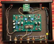
Just finished the B1 and had a couple questions regarding the microphonics. I lined the bottom and sides of the case with Noico, then put a 3x5 inch rectangle on the top panel. Will this cause any overheating? I was most worried about the top piece. I assume the nutube doesn't get too hot since people put erasers on it, but I wasn't sure about the rest of the components.
Attachments
@ SonnyMarrowJust finished the B1 and had a couple questions regarding the microphonics. I lined the bottom and sides of the case with Noico, then put a 3x5 inch rectangle on the top panel. Will this cause any overheating? I was most worried about the top piece. I assume the nutube doesn't get too hot since people put erasers on it, but I wasn't sure about the rest of the components.
Congratulations neat DIY build!
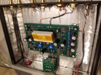
In my build the only little hot component are 270R power resistor
all others passive components and active ones:
jfets and Nutube stay cold after many hours of music session.
No worry nothing be overheating.
After voltages tests preamp does the best sound with sealed enclosure.
Have a nice day 🙂
I would like to point out again that the diagram of Papa and the PCB of Diy-Audiostore are different.
Question whether this is relevant?
Thank you.
...
Hi, I noticed that, too. (Thus my visit to this thread.)
Short answer is that it shouldn't matter. This is based my rather limited electronics knowledge. Transistor Q2 forms a current source. The 1K resistor looks like it serves the same purpose as a grid stop resistor. So, maybe it is actually better placed on the PCB?
Maybe someone else with more knowledge can explain?
Hi,
I am happy owner of Papa’s Christmas gift version of Korg B1. Great little pre!
Currently I would like to repurpose it as an input buffer/h2 generator between dac/pre and diy class D amp (based on IcePower 1200sa2) to add a little of “color” to the sound
The whole chain would look as follows:
DAC/Pre (RME ADI-2 DAC) -> B1K -> class D amp -> KEF R500.
I have a couple of questions to more experienced builders:
1. Would it be enough to just remove volume pot from B1K or should I replace it with a fixed resistor?
2. Are there any other required changes I should consider?
Thanks!
Hi
I would say put some resistors instead of the pot as the B1K might want to see some load, but not an expert on all this.
Othet than that it looks straight forward to me.
Let us know if you are happy with the result
MFG
Claude
I would say put some resistors instead of the pot as the B1K might want to see some load, but not an expert on all this.
Othet than that it looks straight forward to me.
Let us know if you are happy with the result
MFG
Claude
DAC/Pre (RME ADI-2 DAC) -> B1K -> class D amp -> KEF R500
I've done a similar thing, but I used a B1K as buffer between DAC and another B1K. The DAC is a Soekris dam1021, which has unbuffered outputs. So I connected these ones to the input of the first B1K. Then from its outputs to another B1K used as pre. Than a class D amp. The setup works really well!
To be honest, these transformers are from China. I saw them the first time when I was looking for a good dac project and I met the puredsd project. They were used in this build. So, needing to obtain balanced signal from se, I ordered them, but when Italy we were fully locked down. I waited for them for so long (about five months, if I remember well) that I almost forgot that I've bought them. Their delivery was a sort of surprise. Rebuilding the pre, I decided to give them a try and I have to say that they work quite well and surely do their own to make my pre sounds good!
Gaetano.
Gaetano.
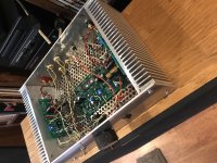
Driving my ACA with the B1. Built it as an integrated amp. I really like it.
But I hate soldering those little tiny pins for the Nutube!!!!
I can't hardly even see them!!!
Thanks for a fun project.
(BTW, I've been complimented that my builds look like rat's nests, thank you.)
But I hate soldering those little tiny pins for the Nutube!!!!
I can't hardly even see them!!!
Thanks for a fun project.
(BTW, I've been complimented that my builds look like rat's nests, thank you.)
Attachments
Last edited:
No danger of overheating from that. Only danger is when cathodes are orange,
with or without insulation.
with or without insulation.
- Home
- Amplifiers
- Pass Labs
- B1 with Korg Triode