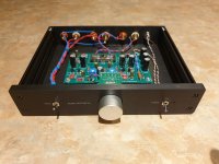
Driving my ACA with the B1. Built it as an integrated amp. I really like it.
But I hate soldering those little tiny pins for the Nutube!!!!
I can't hardly even see them!!!
Thanks for a fun project.
(BTW, I've been complimented that my builds look like rat's nests, thank you.)
Actually, given how rusty I am on soldering and how busy I am, I wonder if I could get someone to built the kit for me. I got it from the DIY store.
Now, don't blame me, I would love to do it, but working from home all these months I'm finding that we're putting like 60 hours a week and the last thing I want to do is spending more time in the home office (where I got the bench) than I have to.
No danger of overheating from that. Only danger is when cathodes are orange,
with or without insulation.
“Heaters” set time your recommendation.
BTW wired it up straight. Invert to invert. So in phase. Didn’t follow the ACA instructions.
Dan
Dan
Driving my ACA with the B1. Built it as an integrated amp. I really like it.
But I hate soldering those little tiny pins for the Nutube!!!!
I can't hardly even see them!!!
Thanks for a fun project.
(BTW, I've been complimented that my builds look like rat's nests, thank you.)
I've printed two copies of the B1Korg build guide by mistake. I hate waste and don't simply want to throw the second copy in the recycle bin unused. Would anyone like the spare copy posted to them?
..what are those resistors?
Red ones are made by Precision Resistive Products (PRP) is an American company based in Mediapolis, Iowa.
Actually, given how rusty I am on soldering and how busy I am, I wonder if I could get someone to built the kit for me. I got it from the DIY store.
What about a local junior high school kid; both of you could benefit !
Switched on this morning and no magic smoke, so a good beginning.
All test points from T1 to T7 reading as they should and a nice glow from the left side heater. The right side illuminates initially and then dims after a moment. The voltage on T8 at the mid-position on the right hand pot is 3.3V. If I turn that pot fully anticlockwise, the value at T8 is 7V at best. The heater glow increases with T8 voltage but still doesn't match the brightness of the left hand one.
I've lifted the board and rechecked all the joints, which were all checked during the initial assembly. I reflowed several which were probably okay anyway, just in case. Same results on powering up after this.
I also checked all resistors before insertion and have rechecked their positions this morning. Everything is in the right place.
HELP!
Or more politely, any suggestions as to the possible cause please?
Attachments
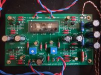
+1 on Sharp eyes Soundhappy
The one on top of your blue adj pot, right side... not sure the only cause but at least a prob
Claude
The one on top of your blue adj pot, right side... not sure the only cause but at least a prob
Claude
Speaking of the blue trim pots, the build guide does not reference any adjustments.
Check the .pdf by Mr Pass in the first post.
Look at 10 uF cap in the center right side have reverse polarisation 🙂
Many thanks to you, Soundhappy. You do indeed have sharp eyes. Having sent the image from my 'phone, I hadn't realised how shakey it was. I completely misssed that. Item turned the right way round and voltages and heater glow matching now.
I am very, very grateful to you.
Time to let it warm up, settle down and hopefully I'll hear some music later today!
Thanks for kind words SuppersReady and ClaudeG.
Please write us more if music at the outputs , hope all is OK now.
Have a nice day
Please write us more if music at the outputs , hope all is OK now.
Have a nice day
Check the .pdf by Mr Pass in the first post.
Perfect. Thanks!
It is indeed producing music. I'm letting it break in on the office system for an hour or two while I sort some lunch. Sounds very promising even through the baby bookshelf speakers.
Thanks again.
Thanks again.
Congratulations SuppersReady!
Just for remembering lot's of sound shape adjustements with trimmers
and reverse phase at power amplifier outputs are possible. Have fun 😀
Just for remembering lot's of sound shape adjustements with trimmers
and reverse phase at power amplifier outputs are possible. Have fun 😀

- Home
- Amplifiers
- Pass Labs
- B1 with Korg Triode